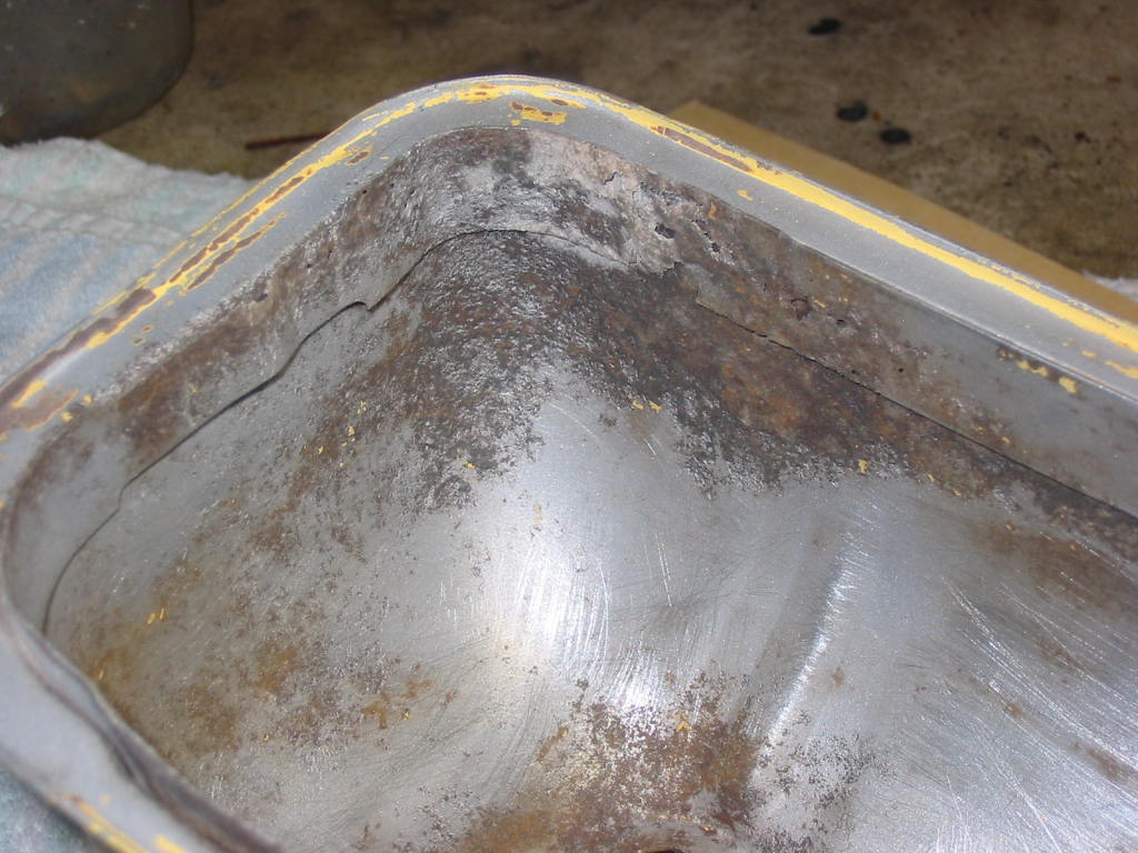
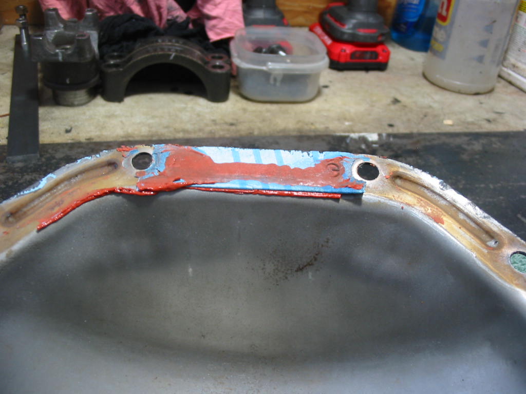
The left cover has a bad section of the inside gasket lip. It’s passable, but not the best.
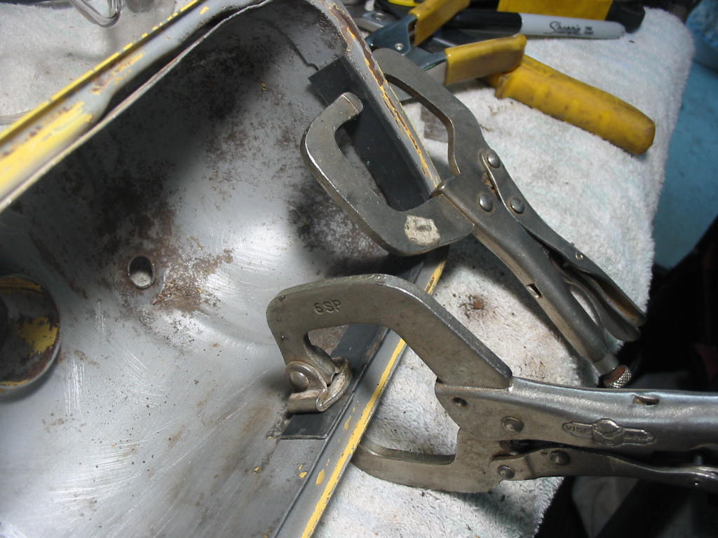
I cut out the bad part of the lip and then cut a strip of 1/32″ steel as a replacement. The corner made it a bit tricky.
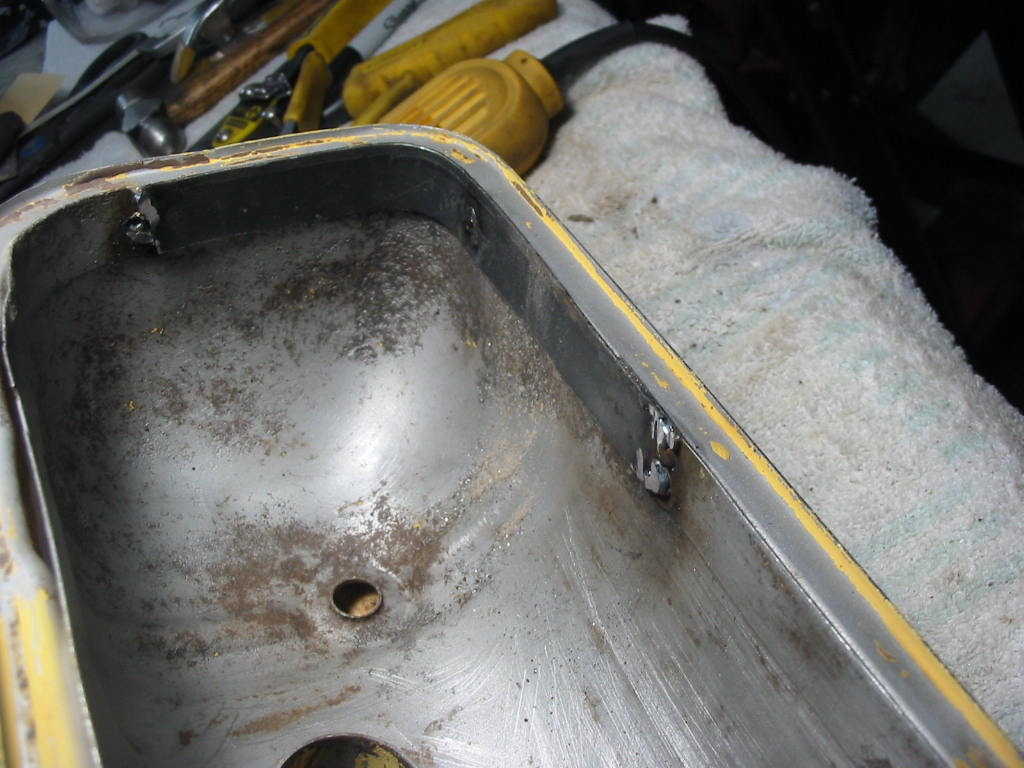
I don’t make any claim to be a welder. I don’t get to do it that much so I trained on a bit of scrap metal before attempting the job. Came out good enough to do the job. I drilled the strip with a 1/4″ drill over the spot where the original spot weld was located – about midway. I then welded the strip at that point as well for a solid fitment.
Sand blasted, repaired, spot weld ridges removed and spot puttied. I’ll leave them for a day and then get to the final sanding.
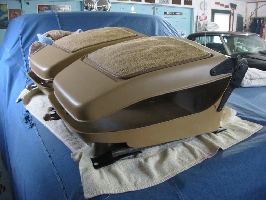
Still waiting for the seats for the Chevy. The upholster lost his helper of 8 years and so is even later than expected. Seats were promised a couple of weeks ago. In this business you need to have patience otherwise best do something else!
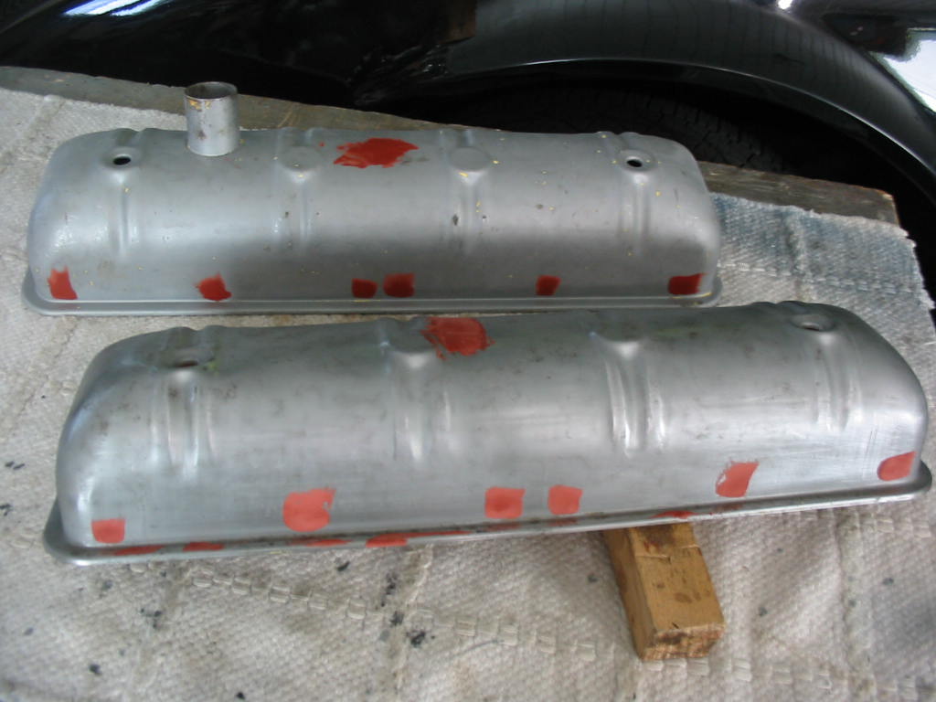
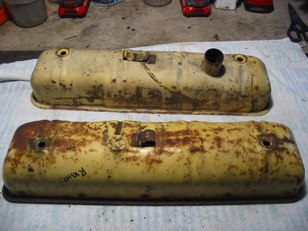
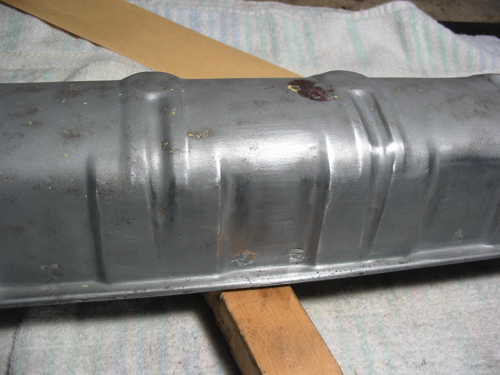
In the meantime I’m restoring a set of Studebaker valve covers. I’ve twisted the spark plug brackets off the top of each one. They are rusted and it’s easier to remove them than repair them. I’ll be doing them up in yellow as was the originals from the factory. My plan is to make them up and let the paint cure longer. Last set I put on before a full cure and the paint took on oil stains that I can’t polish off.
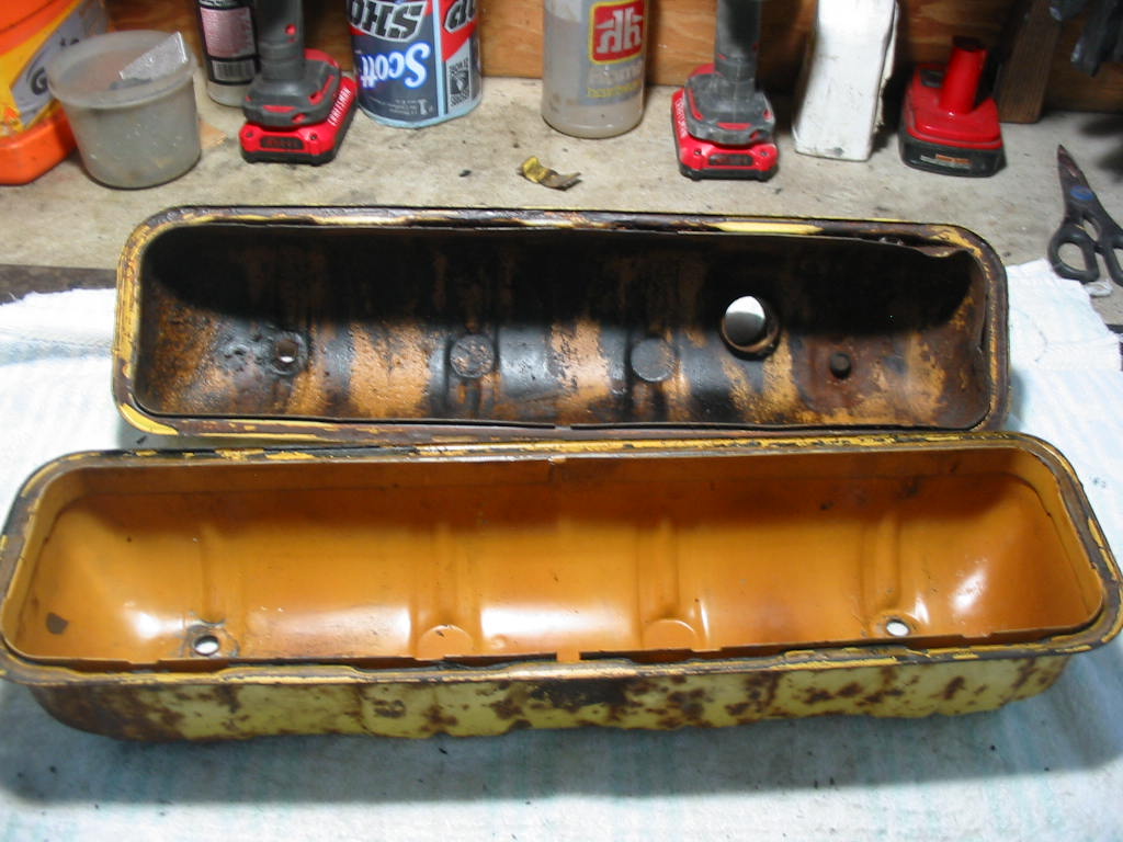
The inside of one is OK, but the other will need to be sandblasted
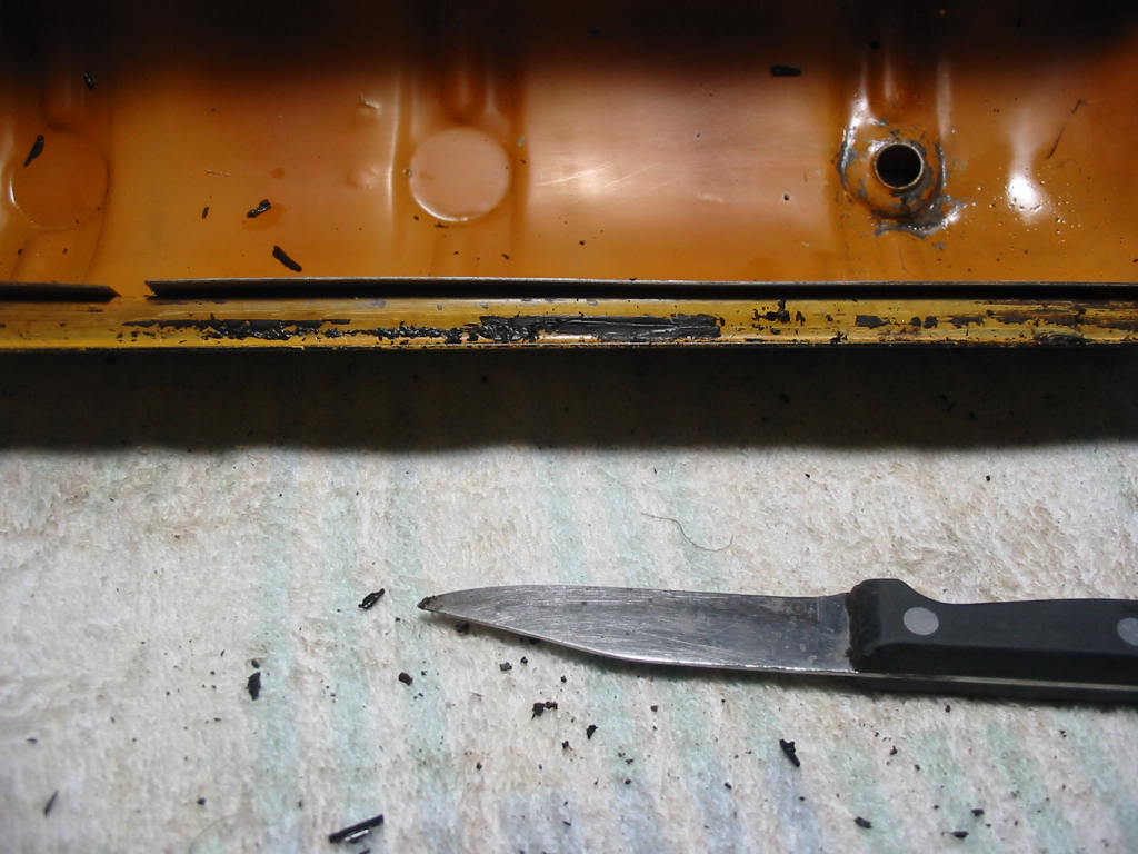
I’ m scraping some of the easy crud off before sandblasting. My equipment is hobby class and so takes a lot to clean off old glue and hardened paint – even with “0” grade media and 100 psi.
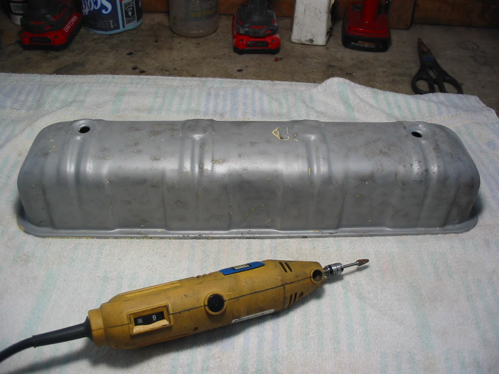
Cleaned up nicely
Next step is to use the dremel with grinding burr to take off the spot weld remains on top and also the ridges and burrs on the spot welds around the bottom that hold on the gasket lip on the inside. The little bits of paint left after sanding blasting I’ll take off by sanding.
Still waiting for the seats for the Chevy. I called and they should be done sometime next week. After that I can get on with shaking the bugs out of the new engine trans setup. In the meantime…
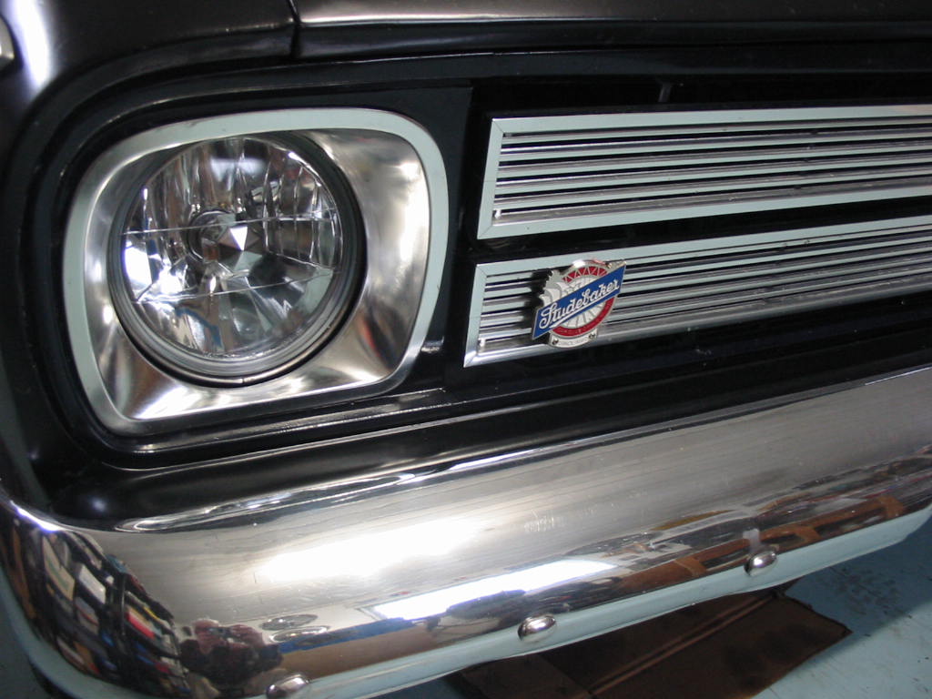
I needed to get a replacement for the 7″ headlight that I burned out last summer. I like to keep one in the trunk. I thought it a good time to switch to halogen lights. I picked these up on Amazon for about 60 bucks. They aren’t a perfect fit, but they worked on the end. The rubber seals over the bulb connector had to be discarded and the bumps on the back of the glass lens didn’t match the grooves in the headlight pot.
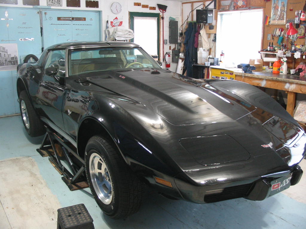
The Chevy is patiently waiting in the background. It will be nice to have it back on it’s wheels!
Cover is back off destroying yet another gasket. The red sealant didn’t adhere to the housing even thought I wiped it carefully with alcohol. I was OK until I torqued the bolts down after waiting 24 hours for the sealant to cure. The torque caused the gasket to split at a few bolt locations and squeeze out from under the cover. I couldn’t take a chance that the same thing was happening on the inside.
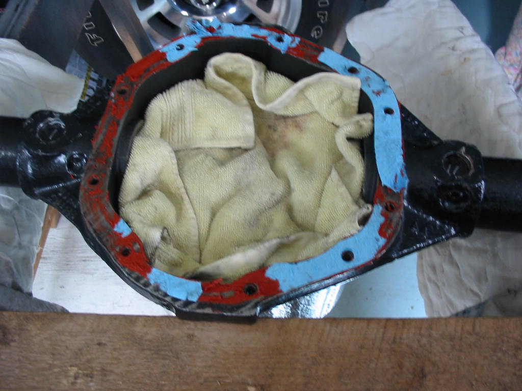
This time the sealant came off the housing with no need for paint reducer to soften it. Oil must still have remained in the metal pores. I managed to keep most of the sealant and gasket bits out of the assembly. I dipped a piece of thin wood dowelling in oil to pick any small bits that got left behind.
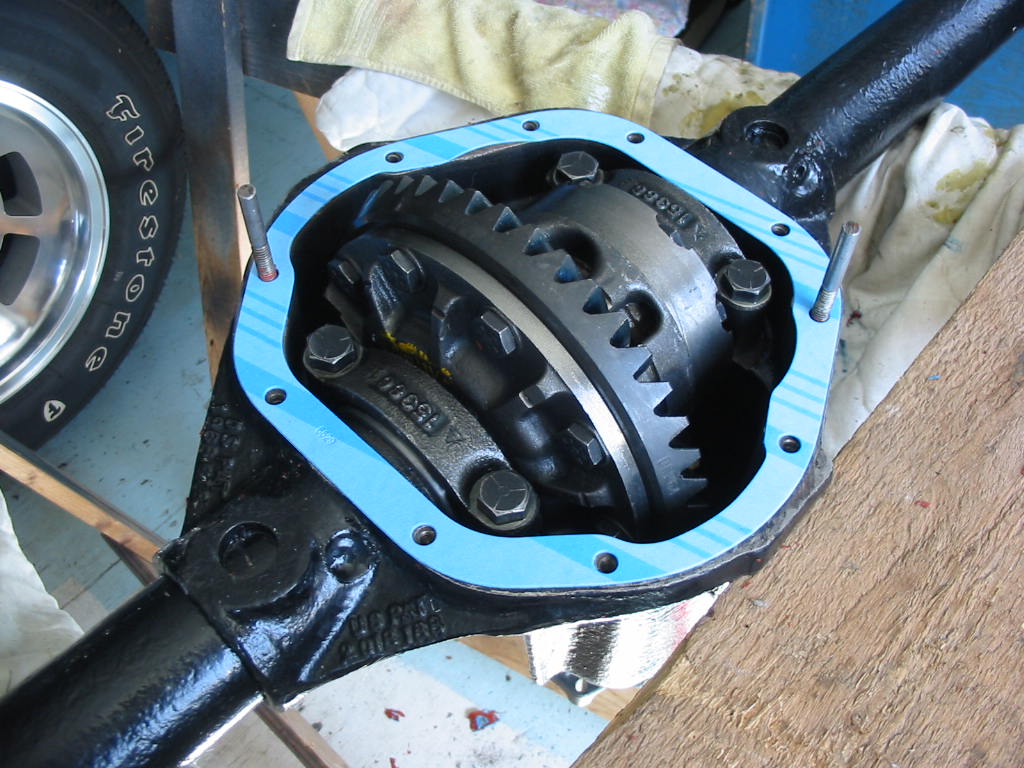
Nice new FelPro gasket – thick paper. I’ll go with a dry gasket this time. If I have leakage problems I’ll replace it with a LubeLocker gasket. It will be easier to replace under the car if there is no sealant to scrape off.
Snugged down and then torqued to 30’# as per the Studebaker Shop Manual for Dana 44 rear ends.
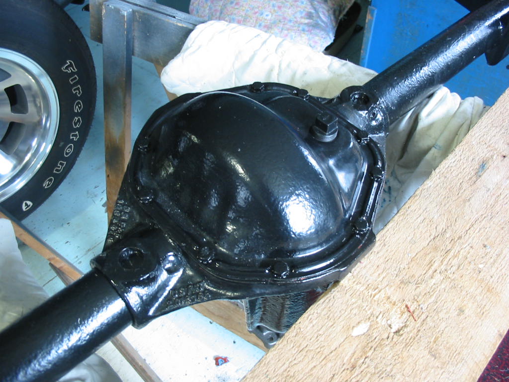
Once again painted up. I’ll now tuck the unit away until next fall/winter when I’ll do the swap.
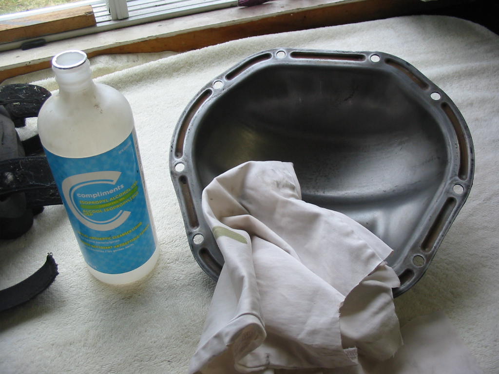
Cleaning up the cover and the matching casting with alcohol.
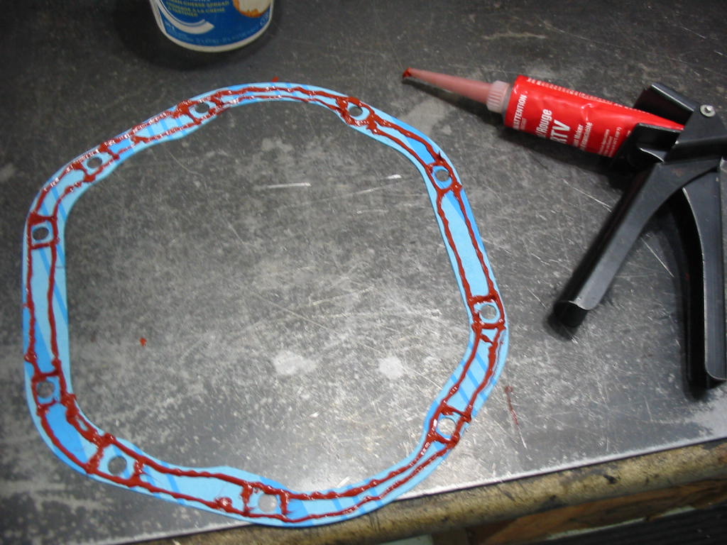
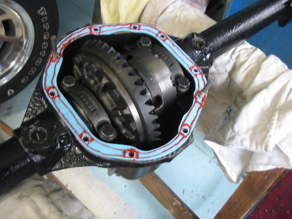
With a light bead of red sealant on both sides of the cover gasket I’m ready to close it all up. Two guide pins in place to keep everything lined up.,
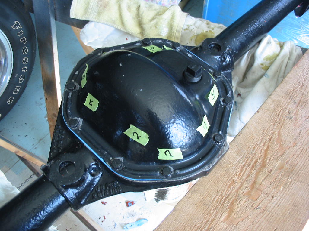
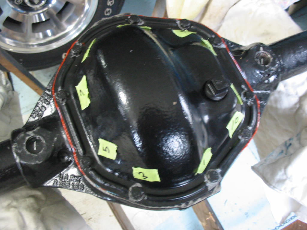
I’ve numbered the 10 screws so that I can snug it all down evenly. Now I’ll just have to wait for 24 hours to give it a final torque.
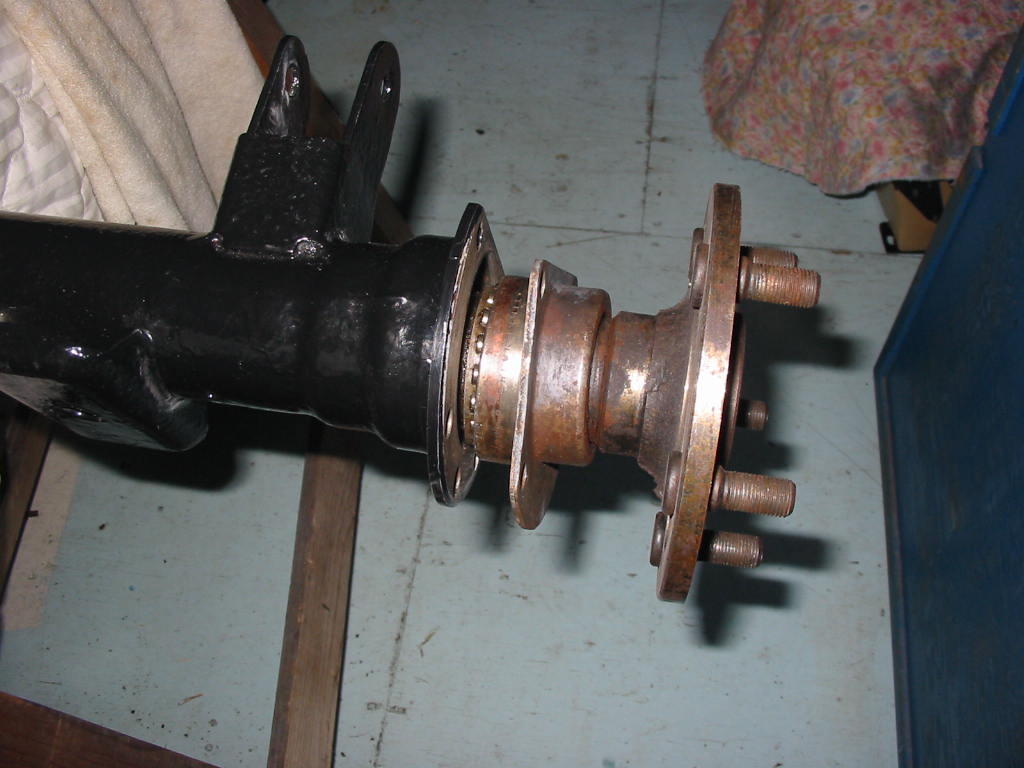
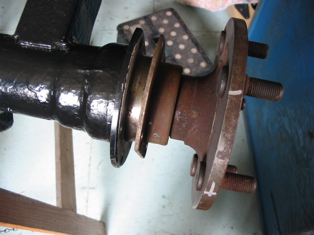
In the meantime I decided to check the fit of the axles. I have a couple of used units for backup. OH NO! the axles won’t fit properly. They won’t go in enough to fit up against the thrust block and the bearings are half out of the housing! Major bummer:-(
Something isn’t right within the TT unit. So off with the cover which destroyed the gasket and leaves a lot of gasket sealant to be removed.
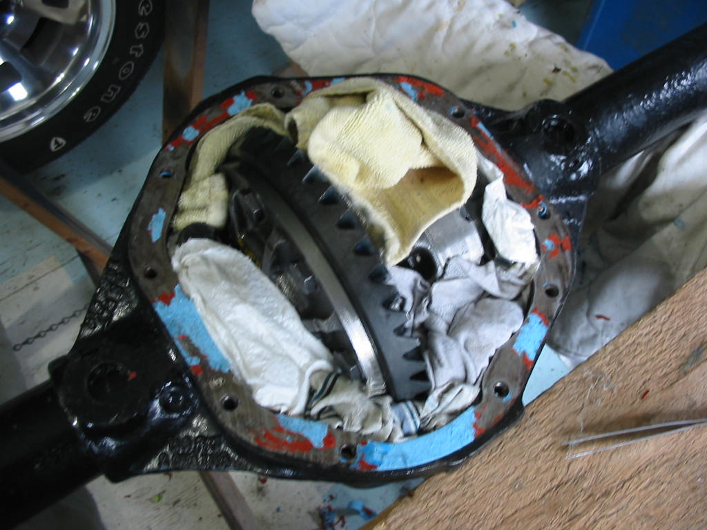
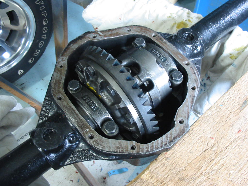
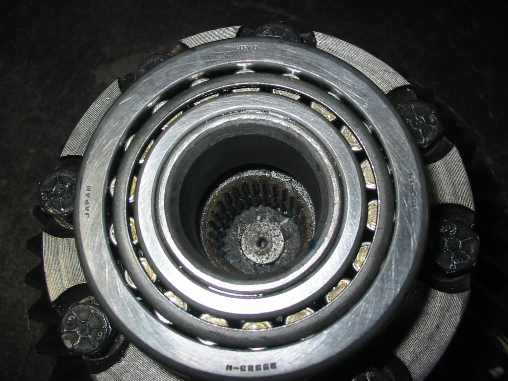
This is where the problem is. The axle shaft has to fit over two sets of splines. One on the spider gear and one on the differential side gear ring. Hard to see, but the two gears are slightly misaligned so the axle slips over the side gear ring, but can’t slip into the spider gear.
I had to loosen all the TT unit cover bolts and then wiggle the axle to get the two splines to line up. I did this on both sides and then re-torqued the bolts to 40’#.
Before replacing the TT unit I had to clear off the old gasket and sealant. I found that paint reducer on a scotch brite pad softened up the sealant and made it a lot easier to remove.
With this done I replaced the TT unit in the differential housing. I then snugged up the carrier bearing caps and put axles in both ends before tightening them to 80’#.
The axles now slip in properly. The bearings are sitting inside the housing – the cup is showing outside only because I don’t want to seat it and then have to borrow a slide hammer to get the axles out again.
A pain in the butt, but a whole lot less so that if I had discovered this problem when the unit was installed in the car. It would have been impossible to do on the car and I would have had to pull the unit out again to work with it on the saw horses. So definitely a silver lining in that cloud!
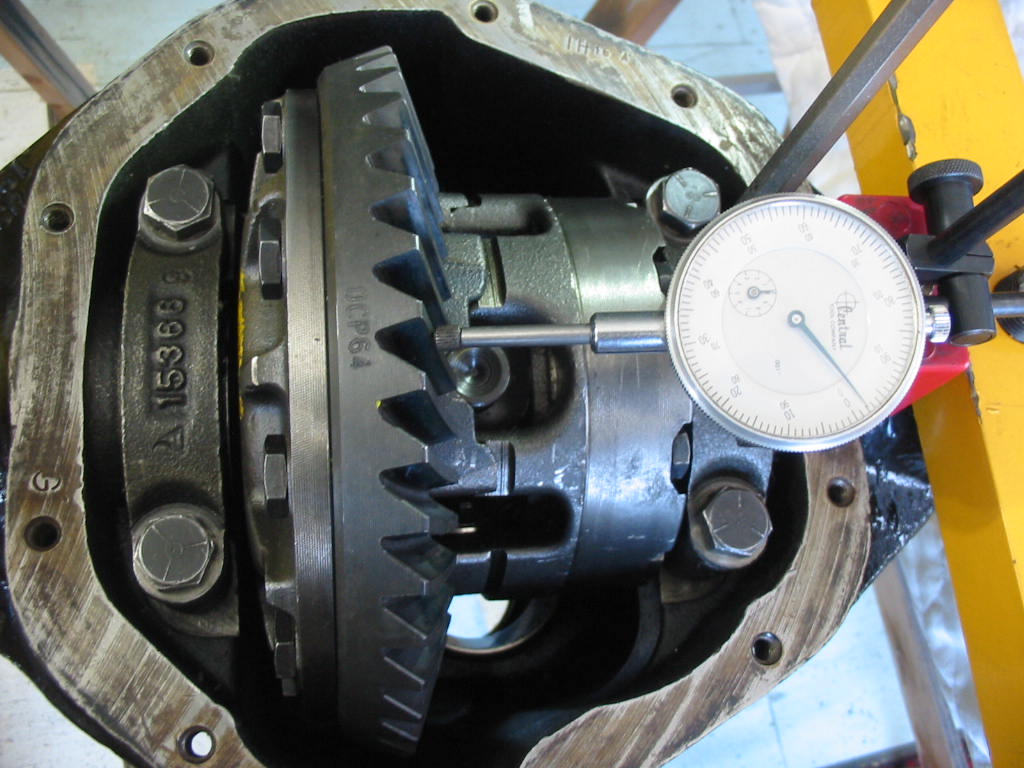
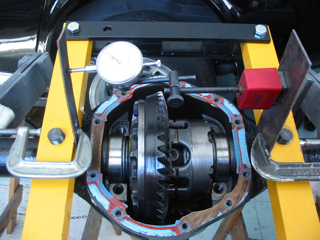
I knew that the gear and pinon turned easily when the whole unit was towards the left. So removed .005 from the left bearing and put it on the right. The unit is shy on shims and so slips in and out of the housing fairly easily. This done and the gear and pinion rotate easily. The gauge tells me that I have about .004 of clearance. I decided to added .002 to both sides before any further tests. With the shims added the unit still slipped in, but with a little more effort. A quick check of the wear pattern showed it was about right. So I decided to add .004 to each side for the bearing pre-load as directed by the Studebaker manual.
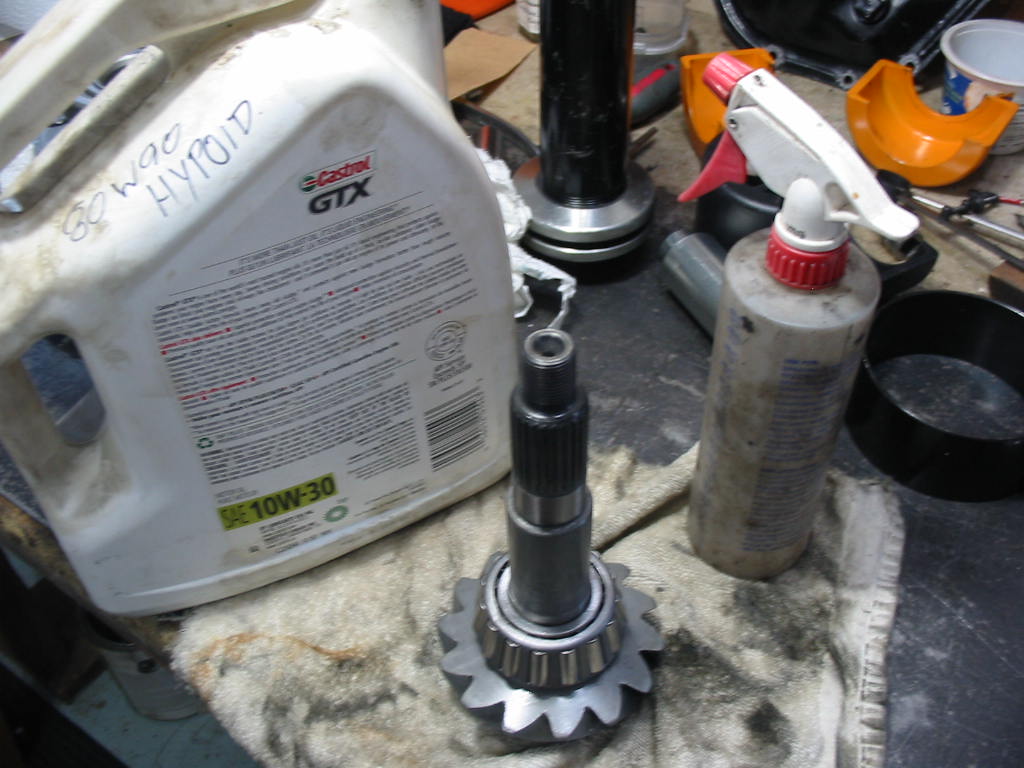
Before I installed the unit with its side bearing pre-load shims I removed the pinion and prepped it for its final install. I had earlier added some shims to the pinion to move the it further into the gear.
During all this work bits of crud and metal may have gotten into the bearings. I sprayed a lot of clean parts cleaner into the pinion bearings and the carrier bearings and then blew them out with compressed air. I then gave the bearings and races a smear of hypoid gear oil.
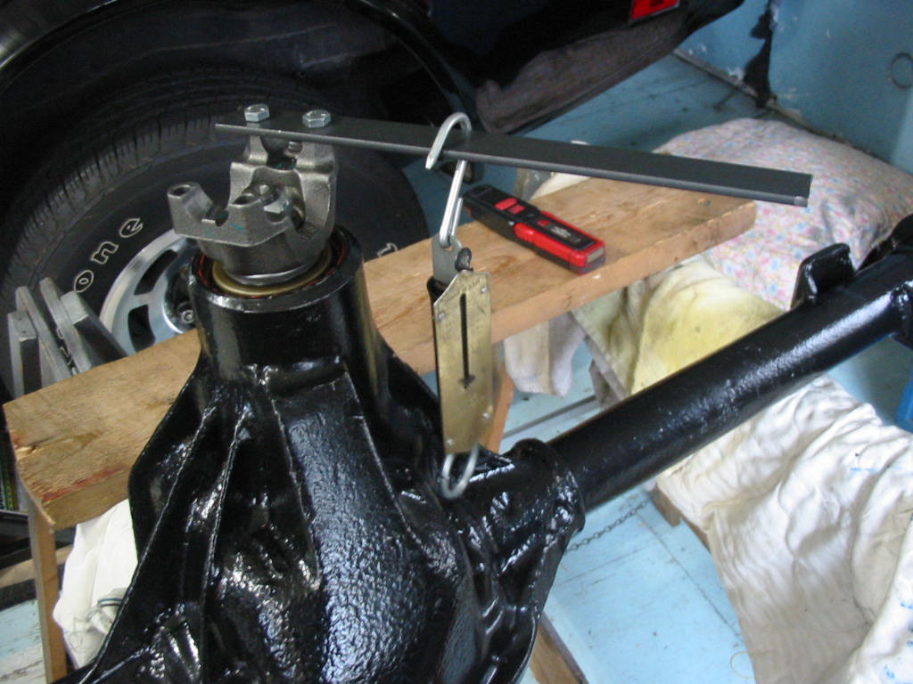
The manual says the preload for the pinion is between 12 and 20’# at about a foot from the pinion yoke. I’m using a spring scale to do the test. Not perfect, but should be close enough. I tightened the pinion bearing nut just enough so that I had a tad over the 12’# (which equals one foot pound weight). I then installed the TT unit with it’s preload shims. I had to use the differential spreader tool this time to get the unit in place.
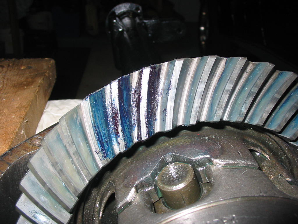
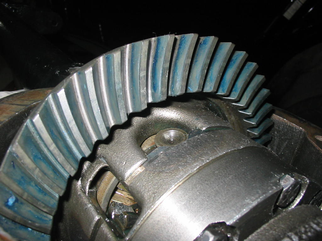
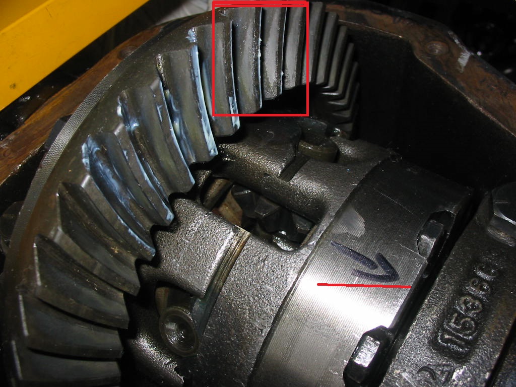
With the TT unit back in place I smeared four of the teeth with prussian blue and spun the unit a number of times using my drill on the pinion nut.
I then checked the wear pattern and it seems good – somewhat in the centre of the tooth and a little down from the top – hooray! I then spun the unit backwards and checked the coasting wear pattern. It was down a bit more on the tooth and a little closer to the tooth toe (inside of the teeth) which the manuals say is acceptable. When spinning the unit I held a gloved had on the unit to give it some drag to show the wear pattern better.
I thought I had a cover gasket, but I don’t so it will be a couple of days before I can close it up. Still waiting on the seats for the Chevy, but I’m hopeful they will arrive before the end of the month.
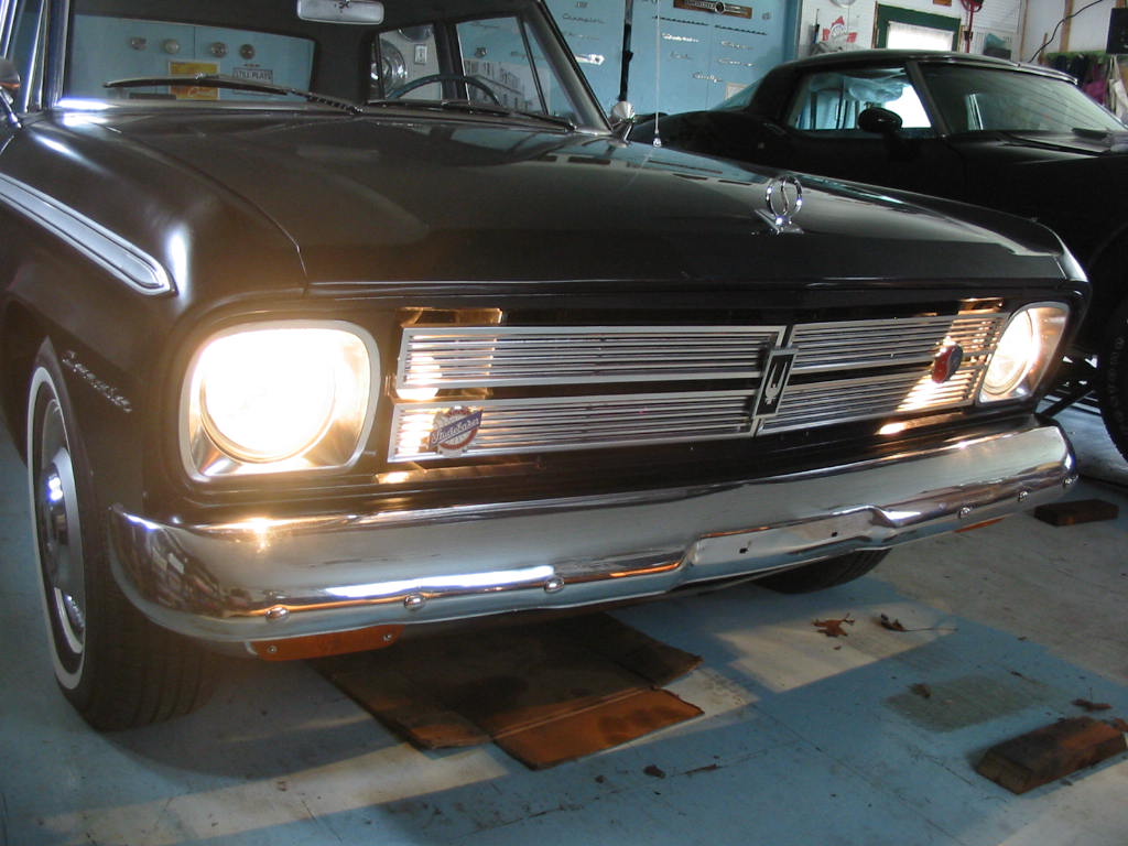
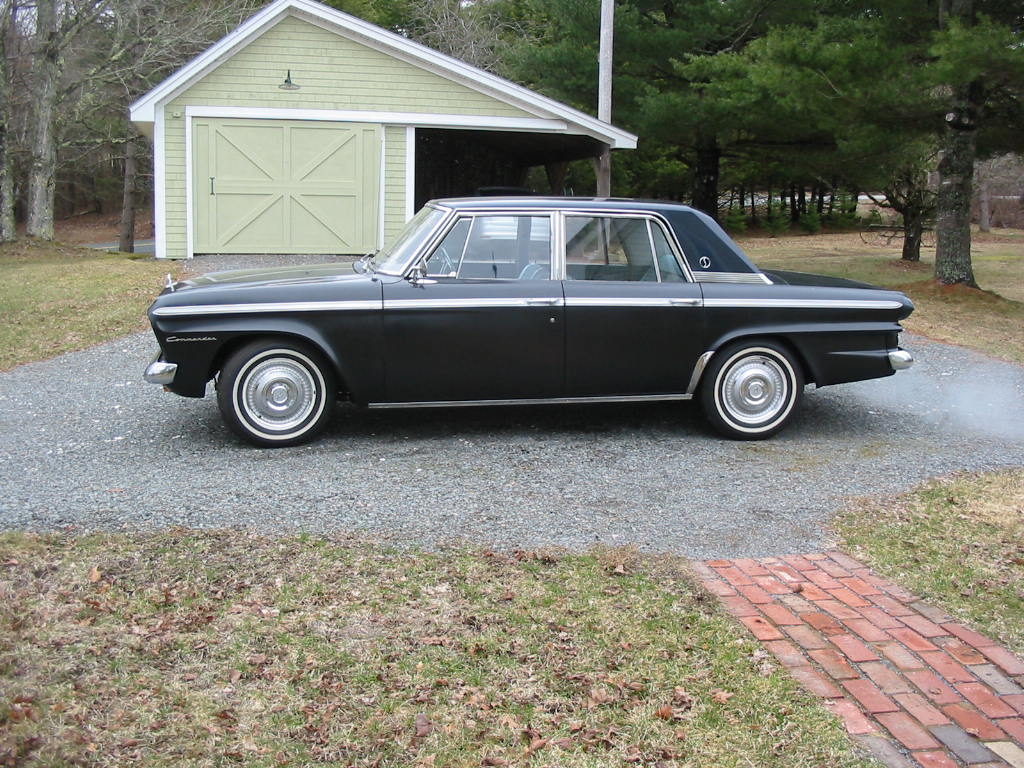
Meanwhile, driving season is just about here and today the roads were clear of salt so I took the ’66 out for it’s initial spin to make sure everything is working OK. All’s good so I’ve got collector car to drive on a nice day. I added the stainless trim under the doors and the rock guards in front of the rear wheels this year. That’s about it for trim. Just need a nice paint job to finish the project:-)
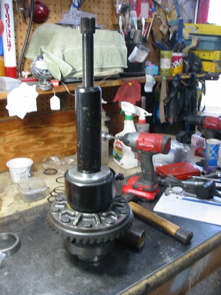
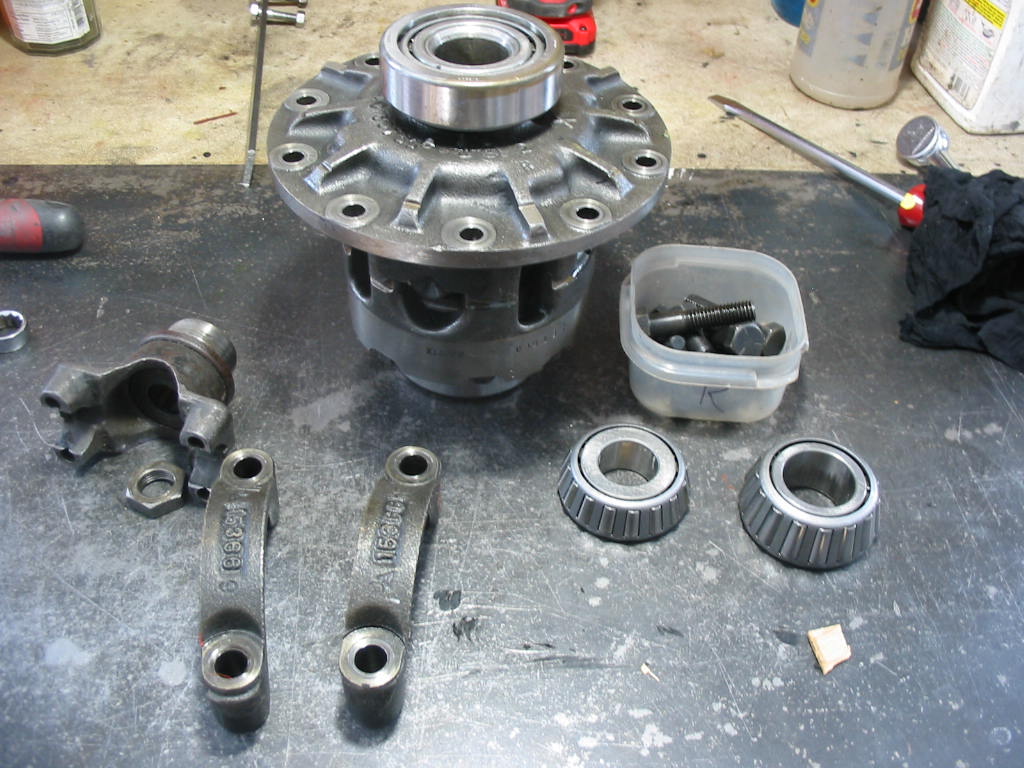
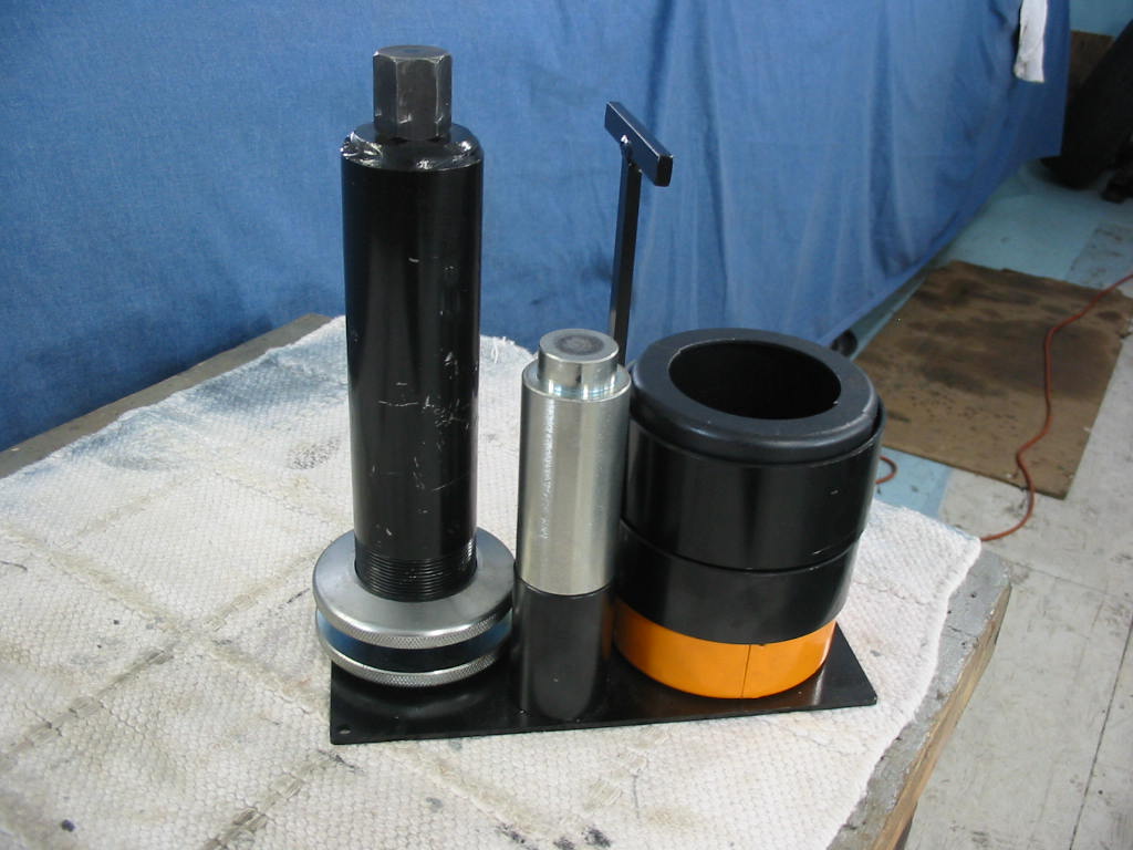
Another must have is a carrier/pinion bearing puller. The bearing have to come off each time the shims are changed from one side to the other. This tool ensures that the bearings are not damaged.
I don’t have a bearing press which would be nice. I can get the bearings on easy enough with a dead blow plastic hammer and this short length of tubing and a small maul. The hammer gets the bearing mostly on and then a couple of wacks with the maul on the end of the tube and the bearing seats fine.
Having problems with the fitting. I started with the shims that were already on the TT unit that I had earlier put together. Some how nothing is going well. The pinion ends up grabbing and the unit doesn’t want to turn. Usually it happens on one spot only. Totally confusing.
Also, I’m having a problem seeing the wear pattern with white grease so I picked up this tube of Prussian Blue from NAPA. Less than $10. So now I’ll remove shims from the TT unit until I get slack without expanding the housing and go from there.
A buddy told of a situation where the ring gear would grab on the case when the carrier bearing was tightened. The 3.07 ring is noticeably bigger than the 3.31 unit. So I ground off a likely spot, but to no avail. It was still grabbing. So back to the easy chair and more thought.
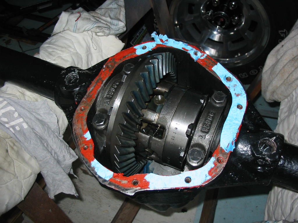
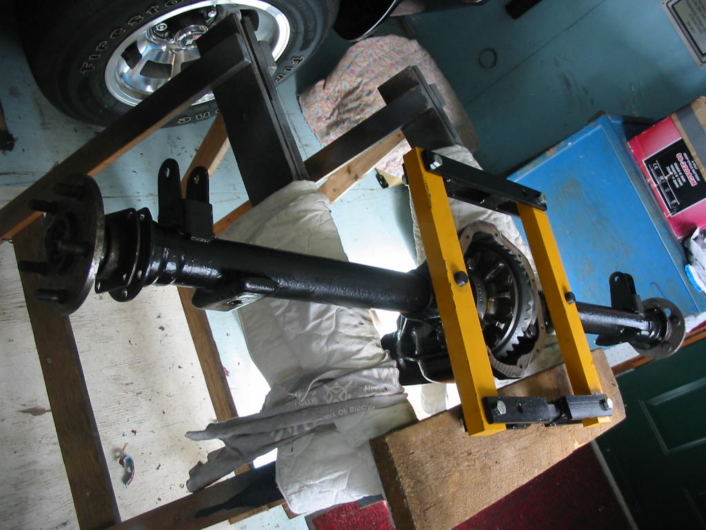
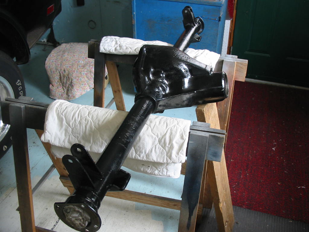
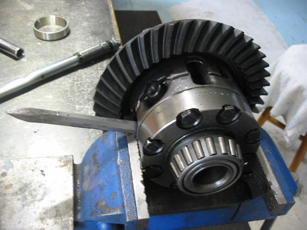
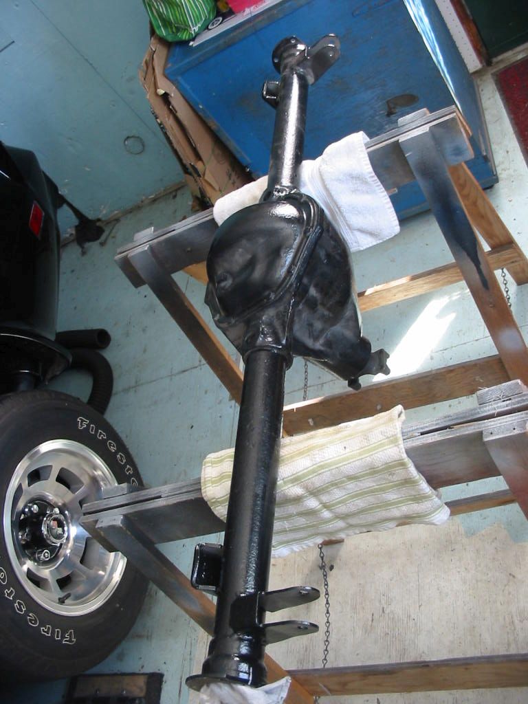
This is a Dana 44 unit that will be going into my ’66 Studebaker Commander. Studebaker used this rear end as did other makers. The rear end in the ’79 corvette is also a Dana 44 – with floating short shafts instead of the axle housings.
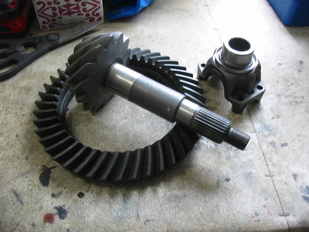
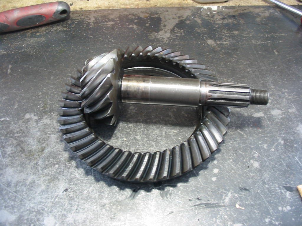
This is a 3.07:1 ratio gear and pinion set going into the Dana 44. It will replace the existing 3.31:1 now in the car. The main reason for using it is that it is the easiest option to lower the revs at highway speeds. An overdrive would be best, but that would involve more modifications than I want to make. This will give me a 7% reduction or a bit under 200 rpm which will give me some fuel savings and more importantly less engine noise (at all speeds). If I want to drive off quickly I only need to start off in L and then bump up to D.
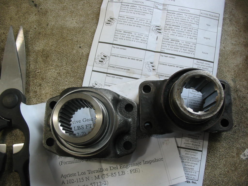
Studebaker used an 11 spline yoke, but I was unable to get a gear and pinion with that count of splines. What is available is a 26 spline unit. Not a problem as I could order a yoke with 26 splines that takes a 1310 universal (3-7/32″ wide with a 1-1/16″ cap) used in the Studebaker.
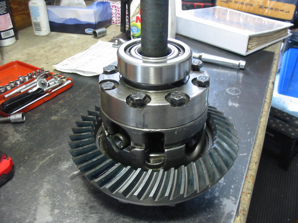
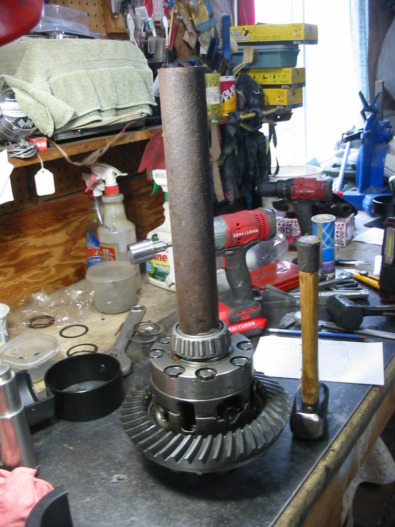
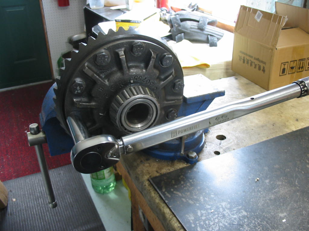
The ring gear has to go on with 80’# of torque. The only way I could hold the unit while I did this was to clamp it in my vice and use a chisel to keep it from rotating – I didn’t want to squeeze the unit too much. Worked quit well. I torqued to 40 and then to the full 80’#.
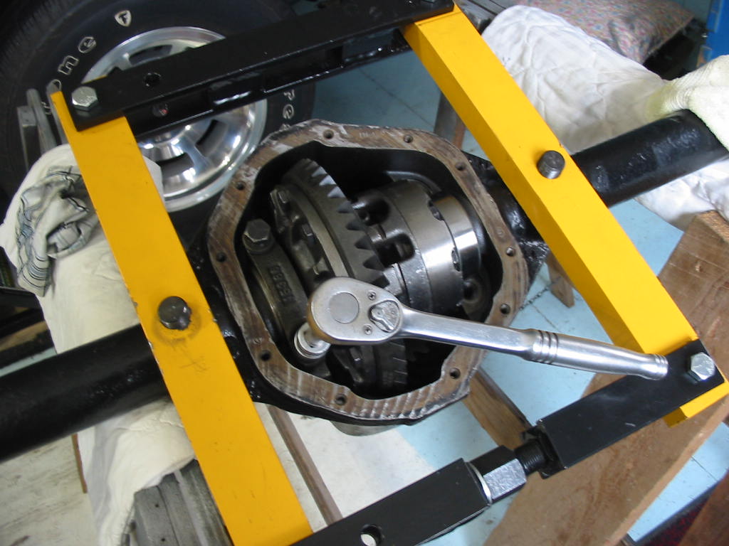
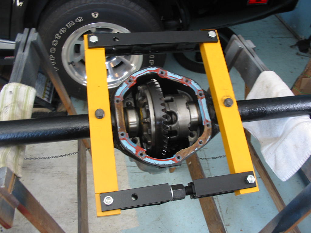
I put the new pinion and bearings in place then spread the case and dropped in the TT unit. The case spreaders are unique to the Dana/Spicer 44 rear end and are a must have to do this job. I only spread the case enough to just get the TT unit in place. Here I’m putting on the carrier bearing caps.
First go around with no shims on the pinion and the original shims with the TT unit. The wear pattern is fairly well centred on the heel and toe but a little high on the tooth.
Next: now the job of Adding a shim to the pinion and moving the TT unit to the right a tad.
Ready for the road -almost. I just need to warm it up and set the timing and that shouldn’t take very long.
I could be held up if the seat cushions don’t arrive in the next week or so. Hopefully Jody will come through.
Next: Once the seats are in place I’ll be getting the bugs out of the engine/trans. Hopefully I won’t have much to report. This summer I’ll order all the parts needed to re-do the front end. I plan to replace all the a-arm and sway bar bushings. I’ll then get it aligned again and the car will be basically done as far as I want to go – unless I go for a paint job.
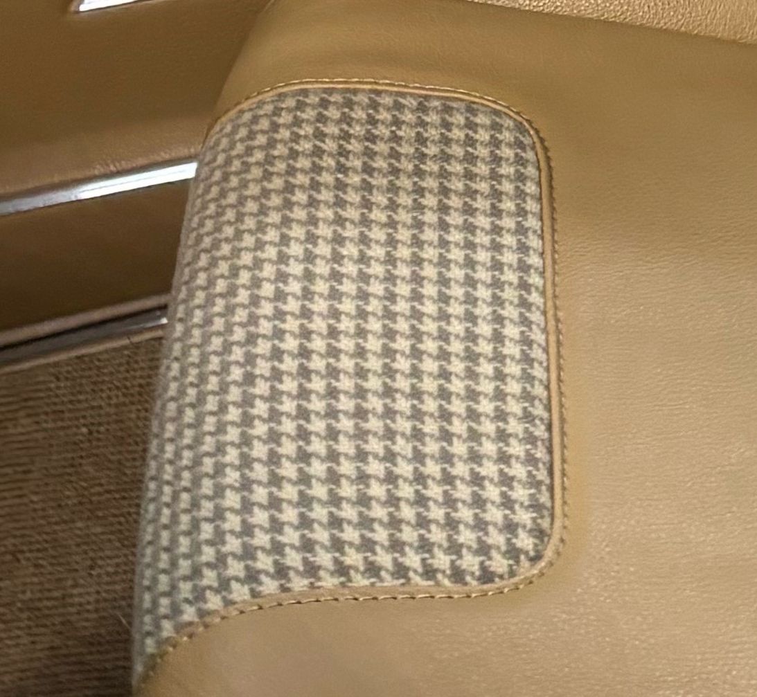
Hooray Jody just got back to me. Unfortunately the fabric I wanted didn’t arrive after 6 weeks so no luck there. As an alternative I picked out a GM-like hounds tooth fabric on the lighter side. I remember the seats in my old ’74 Camaro were black and white hounds tooth. This photo shows the buckskin vinyl and the gray/beige hounds tooth. It’ll take a week for the material to come in and I think I can be hopeful that I’ll see the seat cushions early in April 🙂
Waiting for spring and the seats from the upholsterer, I decided to re-do my Twin Traction posi for the ’66 Studebaker. I earlier built the unit with 3.55 gears. I now want a higher radio than the 3.31 gears presently in the car. The engine is a bit noisy at speed. Going with 3.07 gears will lower the rpm by something under 200 at all speeds. That should noticeably reduce engine noise and give better mileage. The engine is plenty strong enough and if I really want to start quick I can always pull the shifter into low for a first gear start instead of the usual start in 2nd – a quirk of Studebaker Flight-o-matic transmissions.
Good thing I kept my Dana 44 case spreader tool.
The manual recommends that the case be spread a maximum of .020. I found this hard to tell even with a gauge. In the end I just opened it up a 1/2 turn at a time until I could just get the posi unit and ring gear out.
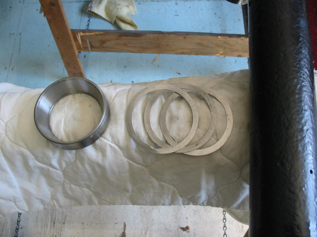
Posi unit and pinion out. So now I have a used 3.55 ring and pinion set for someone. I have the proper bearing remover so the bearings can all be reused.
Cleaning up the cover I noticed that the read sealant was filling gaps in the body/cover surfaces. I’ll be using sealant for sure when I put the cover back on.
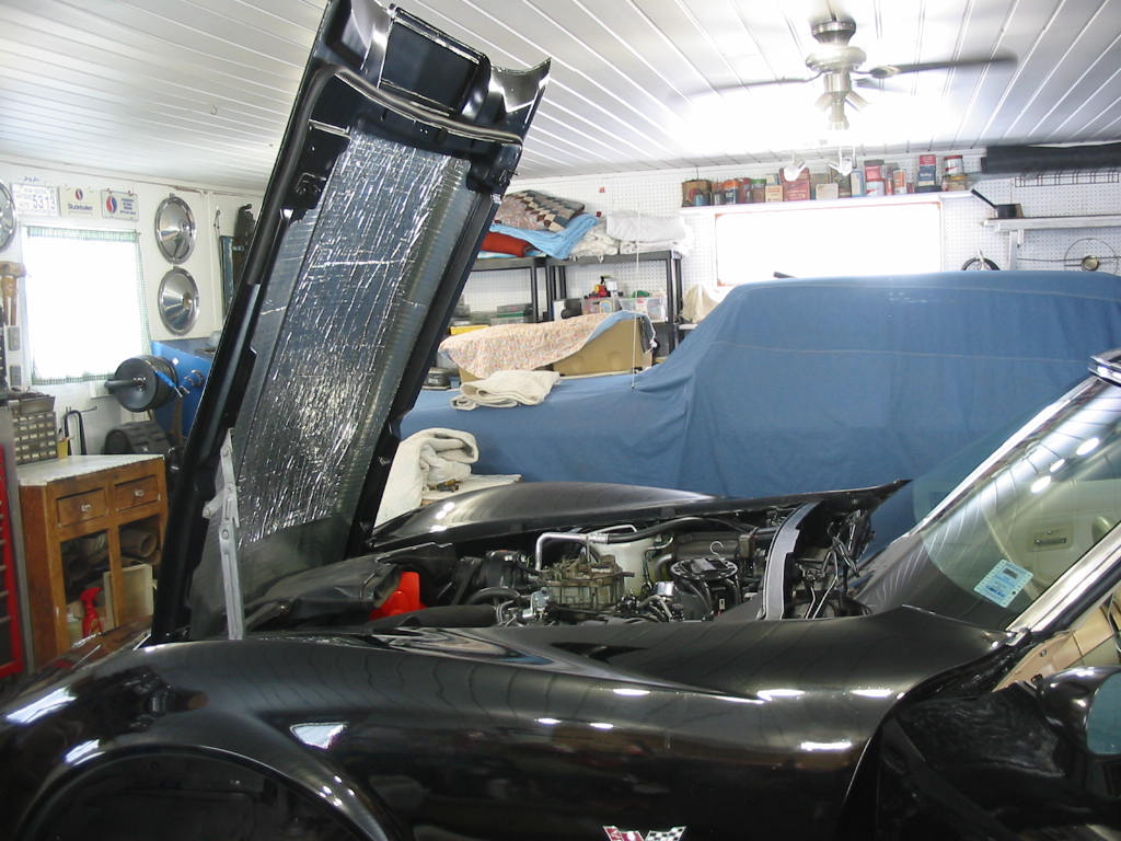
Last job except for the seats is getting the hood back on. With a little help from my coffee buddies it’s back in place 🙂