Still waiting for shims to finish the Dana 44 rear end. Got some from Studebaker Intl and I have some on order from Stephen Allen’s.
In the meantime I came across a used cruise control transducer for CDN $50. So I thought why not collect the parts to give the EL forty-eight cruise. The transducer hasn’t arrived yet, but some parts have. I found a ‘good’ used servo plus brackets and actuating rod. I Won’t be using the blue mount as the one now in place will do fine.
I gave the servo rubber a good coat of silicone inside and out in the hopes it will help it to last longer. The other parts have been bead blasted and I”ll paint up.
Picked up two new speedo cables and a new vacuum break switch for the brake pedal. I also sourced a transducer bracket from Ebay. I’ll get it blasted and painted.
That’s all for now. More as parts arrive. Meanwhile I am driving EL forty-eight to keep things loose, but it’s not really fun with the constant engine miss caused by, I believe, a burnt valve. My donor engine should be arriving anytime.
Studebaker International (one of three large Studebaker parts vendors) can supply the shims for the carrier as well as those for the pinion cup adjustment. Will likely take a week or so to get as I ship by the postal service rather than pay for couriers who add brokerage fees to bring stuff across the border.
I picked up this tool some time ago on Amazon. It’s a spreader for Dana 44 type rear ends. I will need it to put the final shims in for the carrier as the width with the shims will be .008 over the space in the differential casting. This is to preload the bearings on either side of the carrier. I read that the housing can be spread apart a max of .020. I will need most of that to slip the carrier in place.
Something missed from the last post. The spider gears and pinions were a bit grungy and has to be cleaned up before re-assembly. I opted to use rags to wipe away all the dirt. Surprised that so much had accumulated.
To start I installed the new bearings on the carrier without any shims. I don’t have a big enough press so I put the bearings on using an old bearing cup and hammer. Works well with a little grease on the inside of the bearing and on the housing.
Used 3.54 ring gear installed with bolts tightened to 50 ft-lbs. I was a bit concerned that my carrier wasn’t right for the 3.54 gears. Checking on line I found that the carrier break point is 3.73 and lower before a different carrier is needed for 3.92 and higher. The way to tell is to measure between the bottom of the bearing and the flat surface that holds the ring gear. In this case it is a tad over 2″ which is right for 3.73 gears and lower. The measure for the higher gears is about 2.4″
Checking the movement of the carrier sideways.
At this point I have decided to disregard most of the procedures in the service manual. I don’t have all the special tools to follow the instructions which would in most cases would result in a near perfect pattern between the ring gear and the pinion. Instead I am going to adjust the carrier and pinion until I get good pattern between the gears. I will adjust the pinion location by moving the rear pinion bearing race and the carrier side to side with various sized shims keeping in mind I need to have the backlash between .003 and .006.
Checking the backlash.
This is a tool I made up to hold the yoke when I need to preload on the pinion. There is also a preload on the carrier bearings of .008
At this point I have adjusted the pinion closer to the ring gear by about .030 and I have put .020 of shims to the ring gear side of the carrier. This is giving me a nice pattern. Unfortunately I don’t have the shims needed for the right side of the carrier or under the rear pinion bearing cup. I am now stuck until I can get a selection of shims to finish the job.
Next: final shimming to get a nice wear pattern and acceptable backlash.
Clam shell kit I picked up on Amazon for about $200 taxes and shipping in. The black clam shell fits the differential side bearings and the yellow clam shell fits the pinion rear bearing. There are no instructions with the kit so if you are a novice like me you need to watch a couple of Utubes on differential side bearing removal to see how it works. One hint is that you have to have the bearing cups in place before trying to remove the bearings other wise the clam shell just pulls of the bearing cage.
In this shot the housing screws have been removed and I have marked the pinion shafts to be sure and get them back were they were originally. I’ve marked the top of the case, but I should have marked the bottom also.
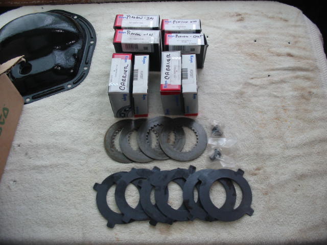
Half the case removed revealing the plate and discs.
The plates are showing significant wear in some spots so I’ll replace them with a new set. The set on one side includes three plates and two discs. The inner plate is concave. I’ll replace the old set with a new set in exactly the same order and per the shop manual.
Carrier all back together with bolts tightened to 50 ft-lbs.
I inserted a flanged axle axle into both ends to align the spider side gear and the clutch friction plates to simplify the axle insertion later on.
Next: time to get the carrier and the pinion in the 44 pot.
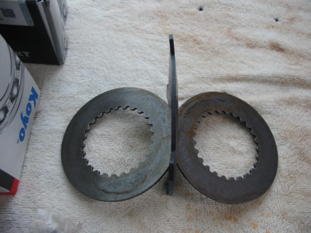
These are the two types of plates used in the TT differentials locking plates and discs. If the plates now in the unit show a lot of wear I’ll do the swap. The angle of the pinion shaft and the matching slot in the TT housing seems to be about 45 degrees which means there should be three or four sets of plates and disks. If that is the case I will need to by one or two extra sets. The parts book only shows sets plus the concave inner plates.
The toothed disks are flat as are two of the plates. The third plate of each set are concave which keeps the disks and plates snug in the TT housing.
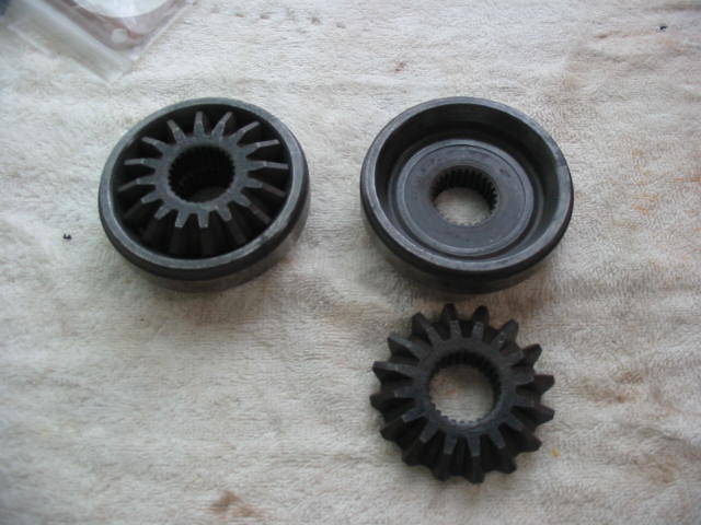
This is a new set of side gears They are for flanged axles and will replace the existing units in the TT assembly that are for tapered axles.
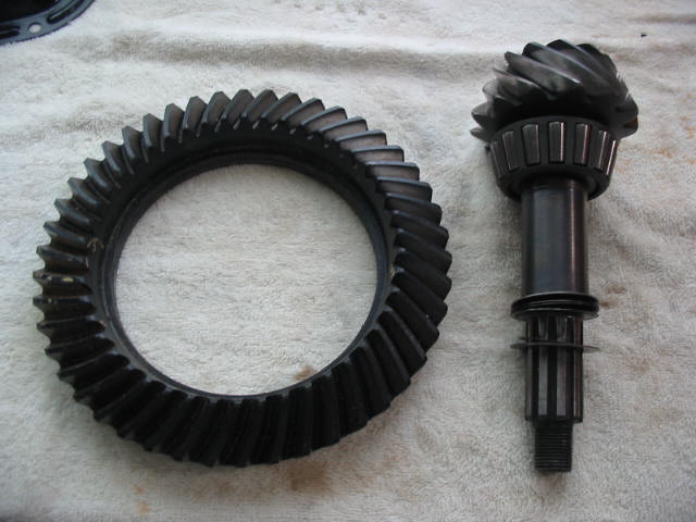
This is a 3.51:1 gear and pinion (used) that I intend to use. It ls slightly lower than the 3.73:1 that is presently in the car. It will give a slightly lower rpm for any given gear and that will reduce noise and improve mileage. The 289 R1 now in the Commander (say something around 220 HP) should handle the change with little difficulty.
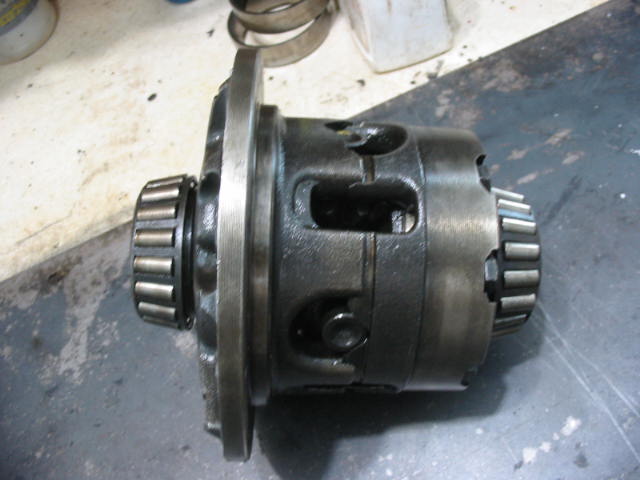
While I wait for my donor engine I’m going to attempt to build a Dana 44 positraction rear end for my ’66 Studebaker. The centre pot and innards of this Dana44 are very similar to the Dana 44 rear ends in many C3 and C4 Corvettes.
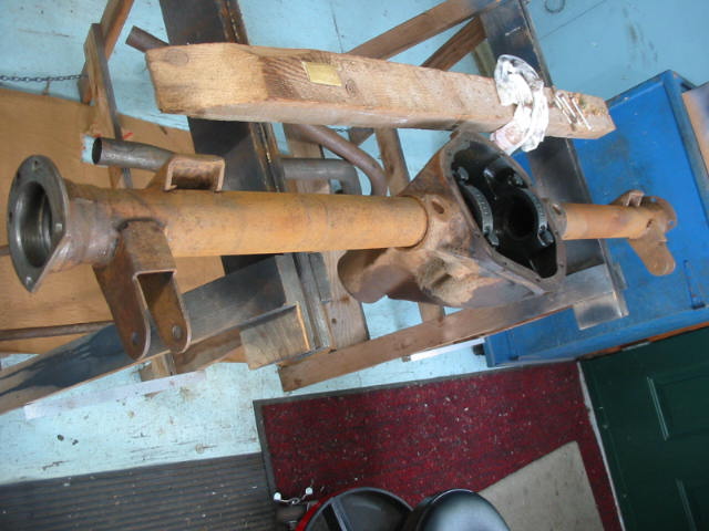
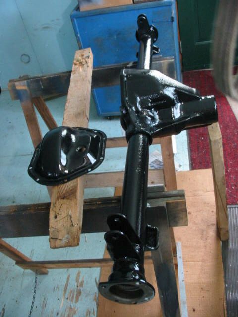
This rear end unit also has the mounts (pointing towards the bottom of the the photo) for traction bars – offered by the factory usually in conjunction with positraction and rear sway bars. Now begins the boring chore of de-greasing, cleaning and painting the donor unit. My idea is to have a complete unit ready to be quickly swapped into the Studebaker whenever I get the chance. Meanwhile it’s the summer driving season and I prefer to keep the cars on the road rather than doing upgrades and repairs.
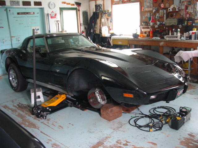
As to the ’79 Corvette, it is laid up. One of the new Firestone tires developed a bubble in the inner sidewall and went flat. More on my dealings with Firestone/Bridgestone later.
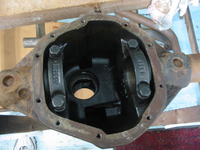
I am beginning with an empty pot. This unit originally housed a positraction unit.
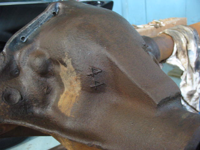
Proof positive that this housing is for Dana 44 units.
This is a Dana 44 posi unit. Very similar to those used in the Corvette differentials. It is a used unit and needs to be opened up and checked. I can’t remove the bearings until I get the special pullers for the job.
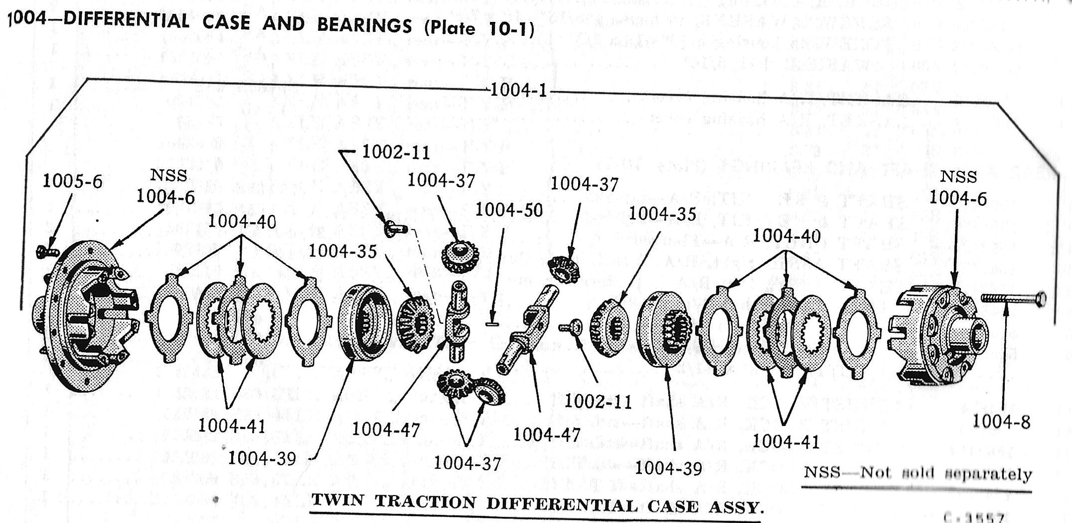
This is the parts book illustration from the Studebaker manual – they called their positraction units Twin Traction. The plates on either side need to be checked for wear.
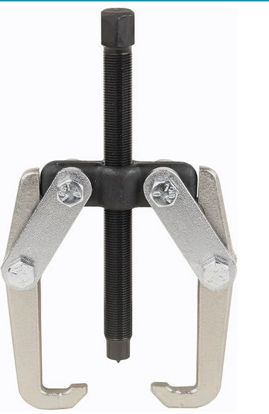
This is the correct puller to remove the bearings and shims from the positraction housing. With to bearings removed the unit can be disassembled and checked. I picket up this unit from Amazon for CDN$124. A lot of money for a puller, but it will prove it’s worth as the bearings may need to be removed and replaced a few times to adjust the shims to give the correct wear pattern on the crown gear.
Black is best! After a good cleaning – last with paint thinners and a tooth brush – it’s been coated with Tremclad rust primer and then gloss black. Tremclad seems to be fine except where the temperatures are getting up to those under the hood. I had problems with the air filter sticking to the base plate where I used Tremclad oil based rust paint.
The kits you can buy to top up your AC gas include a gauge to check the low side pressure (gas coming from the evaporator to the AC pump). According to what I read with an ambient temperature of around 75 F the low side should be between 35 and 45 lbs and the high side between 150 and 170 on a not too hot day. Here the cheepy gauge shows a tad over 20 lbs. By this reading I should be adding refrigerant until it moved into the green area – I had already removed gas at this point. I then connected a set of regular AC gauges I picked up from Amazon for $78.
I also picked up a couple of cans of gas just in case I needed them.
The can on the left is the type that can be removed when partly used and set aside for later. The one on the right is the type that is pierced and cannot be removed. The only way to remove it is to release all the extra gas. A waste and not good for the atmosphere. The AC kit I bought has adapters for both types of cans.
The AC system was originally charged with 134A refrigerant. I couldn’t get any 134A from the parts stores, just this 12A gas which is supposed to be the replacement for 134A and can be used to top up systems already charged with with 134A
Here a low side of about 24 lbs and a high side of a bit over 175 is showing. The AC is blowing cold so I’m happy to stay with the less than optimal low side and a bit up on the high side. I may try removing some gas to get the low side down to around 20 and maybe the high side will drop closer to 170. The low and high settings are dependent on the ambient temperature. I’m using numbers for temperatures of about 75 F. The temperature when I was doing the AC work was maybe a bit higher so the high limit may be fine as is.
The system had upwards of 40 lbs on the low side when I started. That was OK per the gauge that came with the top up can kits. Once the pressure was dropped into the 20 lb range the squealing disappeared 🙂
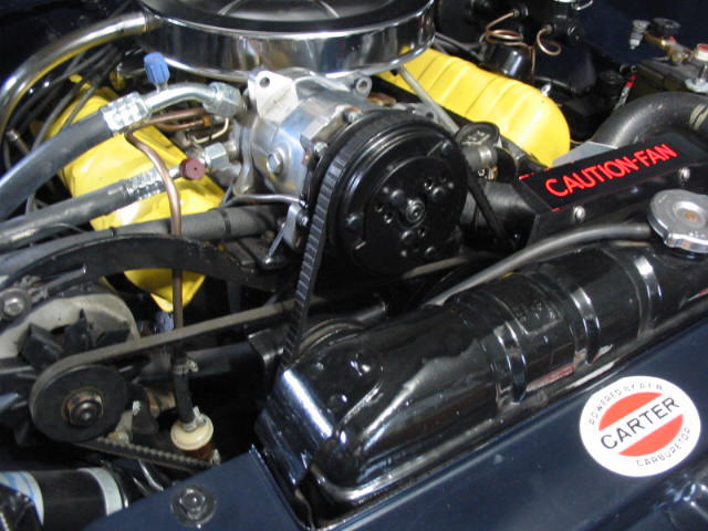
A little while ago I started an item on the AC in my “66 Studebaker. Here is more on my journey to find out where he squeal was coming from when the compressor was engaged.
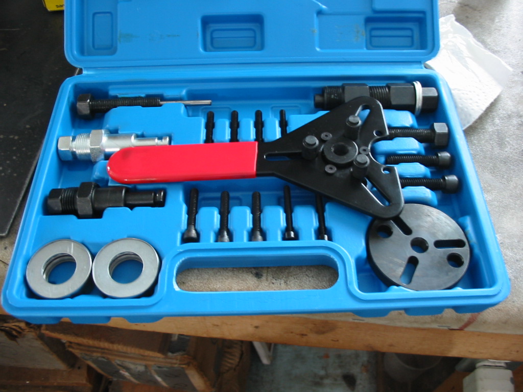
My AC compressor tool kit arrived. A cheapy-do from China, but should be OK for a wannabe mechanic.
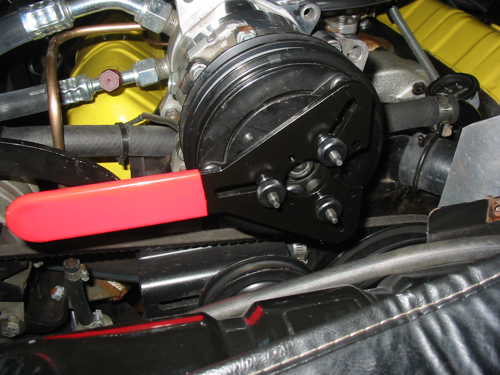
This is the key part that is needed to hold the compressor clutch in place while the centre securing nut is remove.
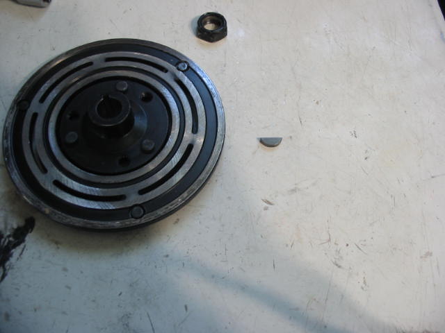
Once the nut is off the puller – see the tool in the bottom right of the took kit – the clutch face can be removed.
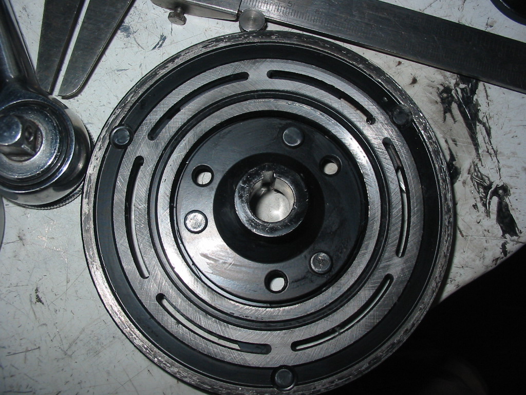
All looks good with the clutch face. Just a light coating of oil. Maybe assembly lube???
The back side of the clutch looks OK too. Also has a light coating of oil. There is a light coating of oil also on the shaft. Notice the nice key slot in the shaft at about 3 o’clock. It is empty! Somehow on assembly it got missed. The centre nut was the only thing holding the clutch face to the shaft. That was OK for quite awhile, but eventually the face began to slip on the shaft and that likely was the source of the squeal.
An old car bud of mine had a little box of various keys in his tickle trunk – perfect fit.
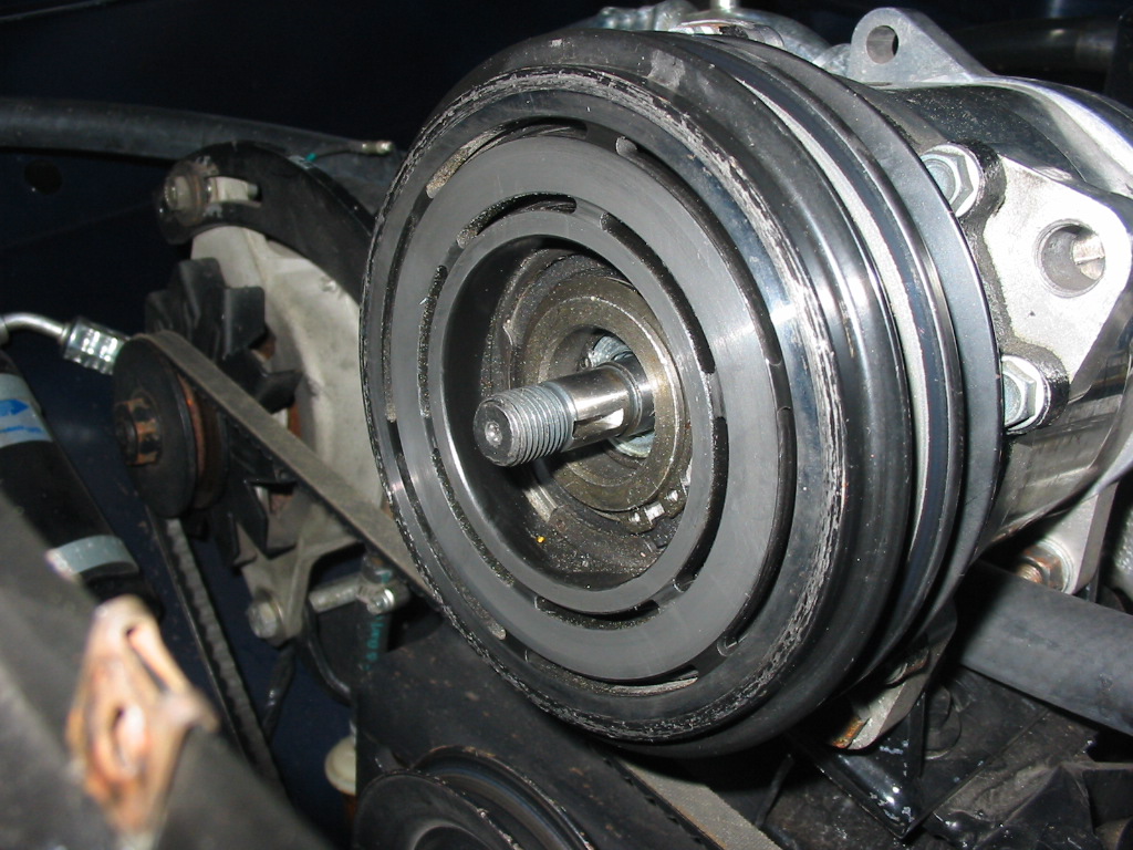
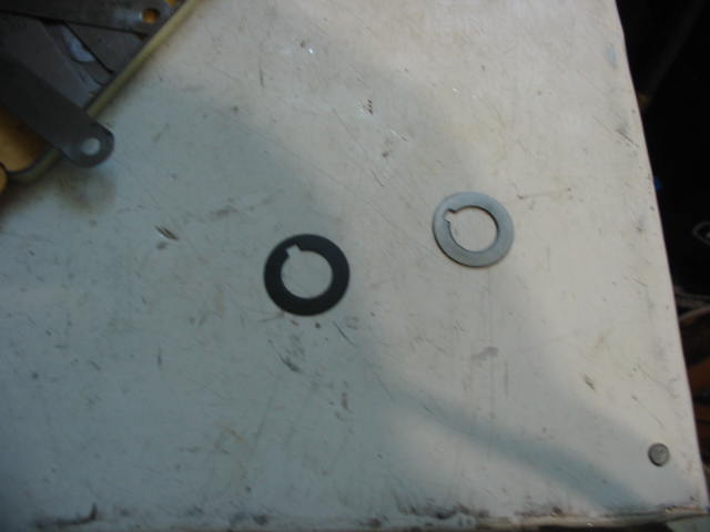
There are two spacers on the shaft to keep the clutch plate a set distance from the clutch face. I decided to check this spacing and found it to be over the limit – .016 to.031. I don’t have other spacers to mix and match so I took the larger spacer and flat sanded it to get a few thou off and get it close to .031.
All back together for the road test. It was a real plus that I could get the clutch apart without only having to remove the drive belt and not the body of the compressor itself.
Time to replace the old vacuum modulator in the hope that it is the culprit causing hard shifts from 1-2 and 2-3. The modulator is at the back of the trans on the passenger side. It’s in a tight spot – crowded by the exhaust pipe (pink on the right side of the photo) which I’m not going to try and remove.
This is the view of the modulator from behind the rear cross member. The screw holding it in place is on the top side.
The only access to the screw holding the modulator in place is with a couple of extensions plus a wobble extension and a 1/2″ short socket.
Got ‘er out. Trans oil dripped out of the opening after I removed the modulator. It lost about a 1/2 cup of oil at most.
New vacuum modulator from Rock Auto. Much smaller than the original. I’ve primed and painted the modulator bracket and screw.
The new modulator being smaller allowed me to get my hand up enough to get the bracket screw started. It was then easy to tighten using my ratchet and extensions from behind the rear cross member. I put a bit of blue loctite on the screw.
All I needed to do then was cut the elbow off the new connecting hose and slip it in place.
I broke the original trans cable when removing it from the manifold bracket. I picked up a new cable from CarQuest and even though it didn’t match the old cable I was assured that it was correct for my year and model. In truth it was not. The old cable had a tension spring that was needed when setting the TV cable to WOT. The new cable slipped in an out easily on the bracket and I couldn’t be sure that I had the correct cable length setting. I found an exact replica of the original on the Northern Corvette website. So I ordered it and got to work putting it in place.
The cable is located behind the two trans cooling pipes. and also behind the exhaust pipe. Ideally you would remove the two pipes and the exhaust. Not going to happen on an engine with 144k kms on it. So I had to get my fingers in with a small 1/4″ drive 10mm socket and remove the old cable. Getting the new cable in place was a bit of a bear as I was working by feel alone. There is also a rubber gasket that needs to fit on the cable end and it of course doesn’t want to stay on the end. But I got it in place after a couple of hours of fiddling.
In order to get the new cable on the carb linkage it’s necessary to remove the TV cable bracket at the rear of the manifold. Other than that it was a breeze to set as per the service manual.
The TV cable has a push up/press down lock. With it in the up position I rotated the carb linkage to WOT which pulled the cable out of the lock at the bracket (I held the coke butterfly open while doing this) and then pressed down on the TV cable lock to set the cable length.
Took it for a test drive and all is good. Passing gear works nicely and I don’t have any fear of trans damage due to an incorrect TV cable setting.
I didn’t clear up another problem that has developed. Shifts from 1-2 and from 2-3 are very harsh. The service manual trouble shooting guide for AT shows that the vacuum modulator is the most likely culprit. Rock Auto has the best price at $58 plus shipping – beats the local parts shops by at least $20. So that’s the next job and it will not be fun getting at it as it is once again tucked behind the exhaust pipe and the rear crossmember is also in the way.
Shaking out the bugs from a car that sat for 20 years!