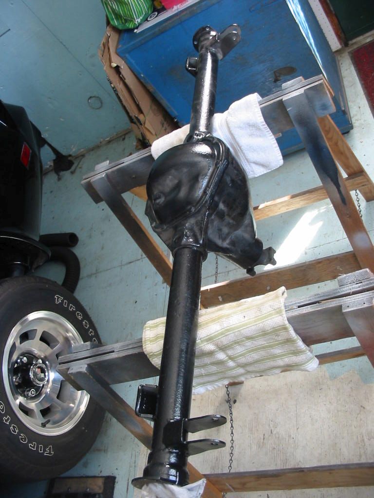
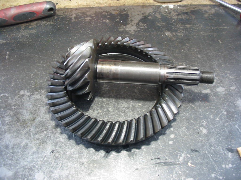
Waiting for spring and the seats from the upholsterer, I decided to re-do my Twin Traction posi for the ’66 Studebaker. I earlier built the unit with 3.55 gears. I now want a higher radio than the 3.31 gears presently in the car. The engine is a bit noisy at speed. Going with 3.07 gears will lower the rpm by something under 200 at all speeds. That should noticeably reduce engine noise and give better mileage. The engine is plenty strong enough and if I really want to start quick I can always pull the shifter into low for a first gear start instead of the usual start in 2nd – a quirk of Studebaker Flight-o-matic transmissions.
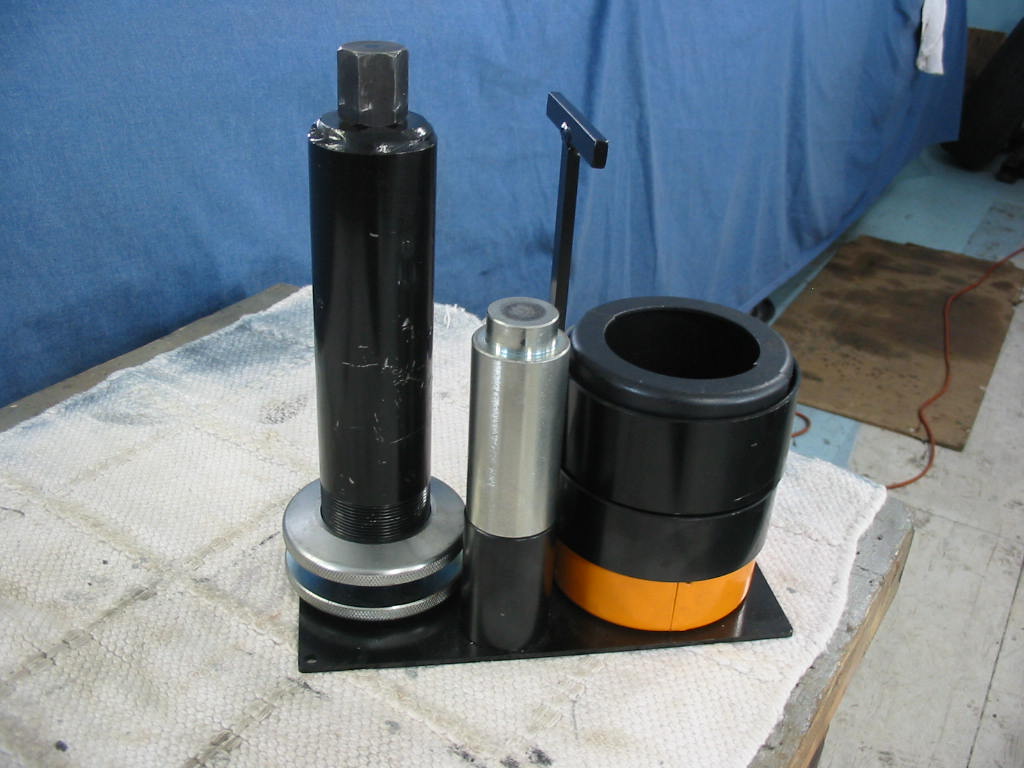
Good thing I kept my Dana 44 case spreader tool.
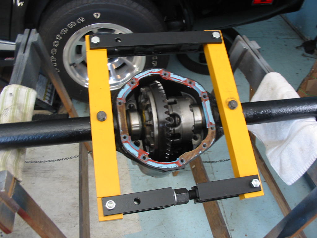
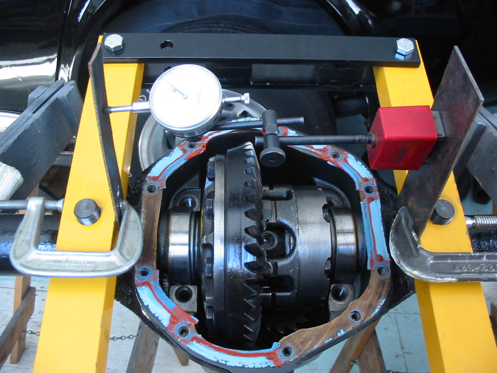
The manual recommends that the case be spread a maximum of .020. I found this hard to tell even with a gauge. In the end I just opened it up a 1/2 turn at a time until I could just get the posi unit and ring gear out.
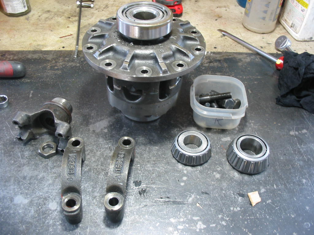
Posi unit and pinion out. So now I have a used 3.55 ring and pinion set for someone. I have the proper bearing remover so the bearings can all be reused.
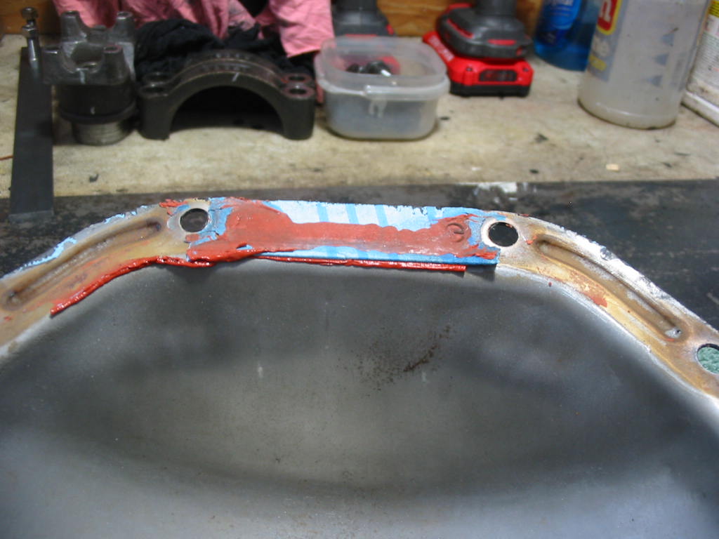
Cleaning up the cover I noticed that the read sealant was filling gaps in the body/cover surfaces. I’ll be using sealant for sure when I put the cover back on.
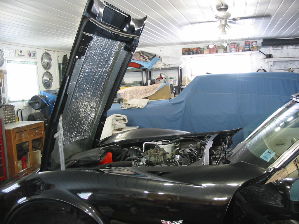
Last job except for the seats is getting the hood back on. With a little help from my coffee buddies it’s back in place 🙂
I have collected some AC stuff over the years – AC testing kit, the usual AC top up kits and a vacuum pump.
This is my setup to vacuum down the system via the connection on the high pressure side. It will allow vacuuming on both sides of the AC pump – both the condenser and the evaporator and dryer.
I’m using the low pressure side gauge as it shows vacuum to 30 #s. Unfortunately it would not hold it’s vacuum, but slowly dropped.
It’s impossible to hear air leaking into the system so I connected up a bottle of R22a and put a small quantity of gas into the system. I actually held the bottle upside down to get the liquid refrigerant into the system.
I then went over all the connections and sprayed them with a little soapy water. I found a spot where bubbles came out under the cap on the low side connection. I took the cap off and replaced the schrader valve.
I then released the gas and vacuumed the system for 45 minutes. After that I let the system stand for an hour. The needle dropped a bit, but I suspect that was caused by my closing (releasing pressure) and then opening the valves to take the pressure reading.
As a last step I again charged the system with a little refrigerant. I’d rather have the system lose a bit of gas rather than have it vacuum in air and moisture. I won’t be charging the system until some time later this summer when I’ve got all the bugs out of the new engine/trans and the temperature gets into the 70-80 degree range.
Hooray! the condenser has arrived and it appears OK in spite of it’s travels. It’s very light, no more than a couple of pounds. The three tabs on each side are to mount the original condenser brackets
Once again the mounting holes are very small – maybe 1/8″.
This time I’m going with the smaller holes. I’ve tapped them out to take a small 1/8″ stainless screw. I’ll install with a washer to fill the larger mounting bracket holes and then add a nut to the under side with Loctite blue to be sure and hold them in place. Three on each side should be fine for such a light condenser.
Small screws and washers holding the bracket and a nut on the back. A bit tight getting the nuts on, but doable.
When I set the condenser in the car I had problems getting the bottom of the bracket to fit its mounts and at the same time fit the top bracket mounting holes. I had to remove the condenser a couple of times and move the brackets in the mounting holes. Not an easy fit as the brackets had to be slightly forced into place, but enough wiggle room to get them in.
Next problem was that the high pressure line was nowhere close to fitting – so out with the condenser once again.
After some bending – without kinking the delicate aluminum piping I got the high pressure line to fit OK. The low pressure input line was much easier being a flexible rubber line. I used new O rings in both. I bought a selection box of AC O rings from Princess Auto some time back and they have been useful. I only set the condenser in it’s rubber bottom mounts before attaching the lines. That gave a little flexibility when making the connections. They have O rings so I only just snugged up the fittings. Stubby wrenches helped on the bottom fitting.
I didn’t like the way The high pressure line was tight against the rad/condenser frame so I cut off a shot piece of fuel line, split it, and slid it down the frame so the line is now protected.
Missed putting back the corner moldings for the lower front rear window trim. Never too late 😉
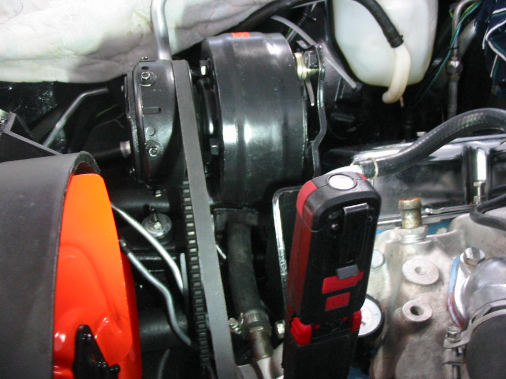
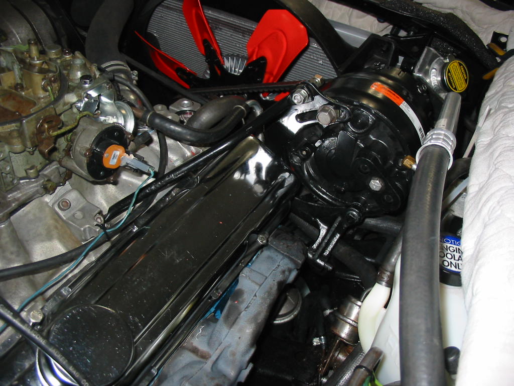
Getting the last of the three belts on the engine to drive the power steering pump. I put a fair tension on this belt so it won’t squeal when turning the wheel to park the car.
I wasn’t going to hook up the AC pump until the condenser arrived. It’s a bit late so I thought I might as well hook up the fluid lines, the electric clutch and the car solenoid – the green wire.
I’ve tied up the rad & shroud to the rad support before I take out the upper rad bolts.
The upper rad bolts – top left taken out – also holds the top of the condenser. The foam is a replacement for the factory seal. There are four – two on the top corners and two on the sides – which help keep air going through the rad/condenser. I replaced them all with some black packing foam cut to fit.
It’s Tuesday after a big storm. The condenser is supposed to arrive tomorrow, but we’ll see. It’s already four days over the original delivery date!
Next: installing the condenser and vacuuming down the system.
Time to put the drive shaft back in. I was careful to mark the shaft and yokes so I could get it back in the same way as it came out. Tight fit at the back. Just enough room to get the bolts back in – 7/16″ fine. The book says 70 #’ of torque. Just now way to do that with my tools. Only enough room to get a 1/4″ drive socket over the head. The saddle prevents using anything thicker like a regular box end. So I just used blue Locktite and a little extension on my 1/4″ ratchet to get it tight – likely about 20 #’ at best. I was able to get a torque wrench on the trans end. Again I used Locktite and only went to 30#’.
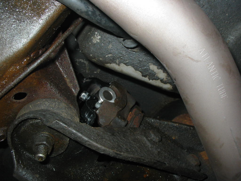
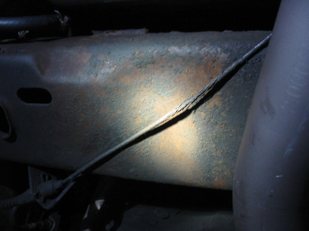
The parking brake lead on the right side was hidden under the old single exhaust pipe. The heat and moisture pretty well destroyed the wire. Chances are it will break, but I don’t want to replace the leads this year so…
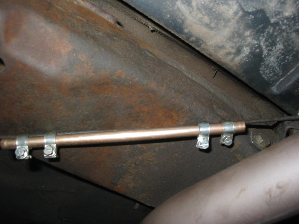
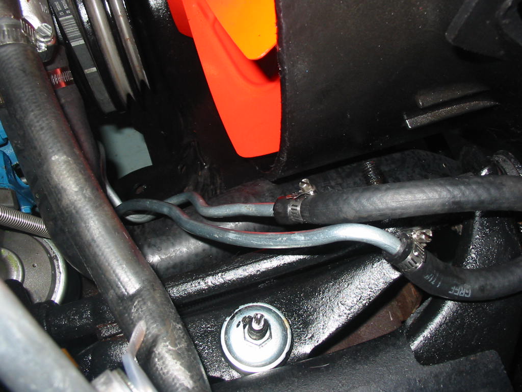
I cut a length of copper nickle 3/8″ pipe long enough to let me use a couple of high pressure clamps on either side of the frayed line. The clamps are squeezing the wire to the pipe. Tested it out and it seems to be fine. I’ll replace it next winter.
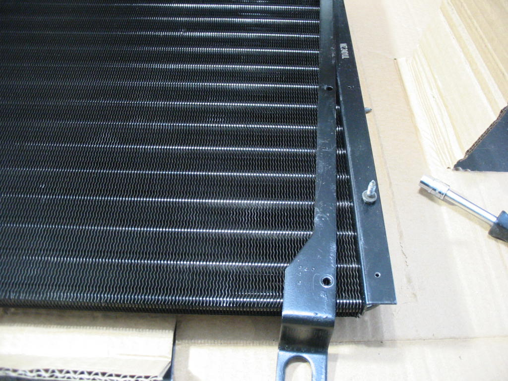
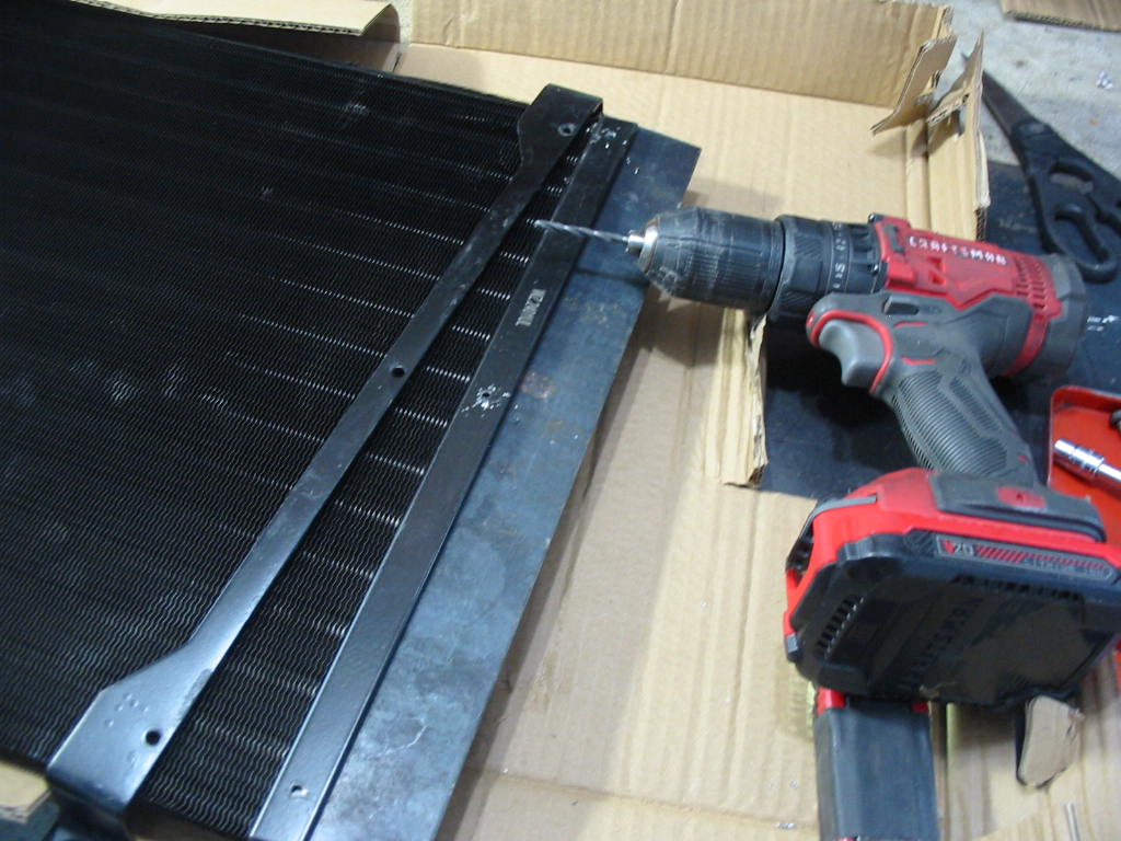
My new UAC condenser can’t accept the original bracket screws. You need to use your old brackets and screws as neither are supplied. The screw holes in the frame are way too small.
I put a piece of flat bar stock under the bracket to keep from drilling into the condenser tubes and opened up all the holes on the left side. It looks like the screws will go in fine missing all the tubes.
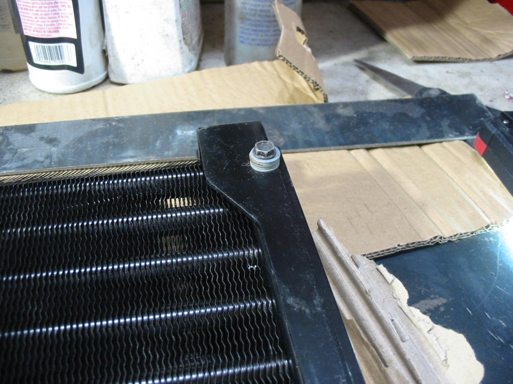
Unfortunately the top screw dug into the inside of the top condenser loop. I would need to put a stack of washers under the screw to keep from damaging the unit.
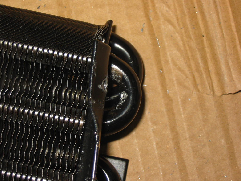
Nothing lost by bending back the condenser frame and checking to see how bad it was. The little black dot in the center of the damaged tube is where a dental pick broke through when I tested it – so toast. I’m not going to try and have it welded. Just too much trouble to have to redo the job if the condenser fails later on when a new unit can be had from Rock Auto (different brand) for $153.61 delivered to my door three days 🙂
Meanwhile I can get the compressor back in place.
Installed with all the brackets in place. I’ll hold off connecting it up until I get the new condenser installed.
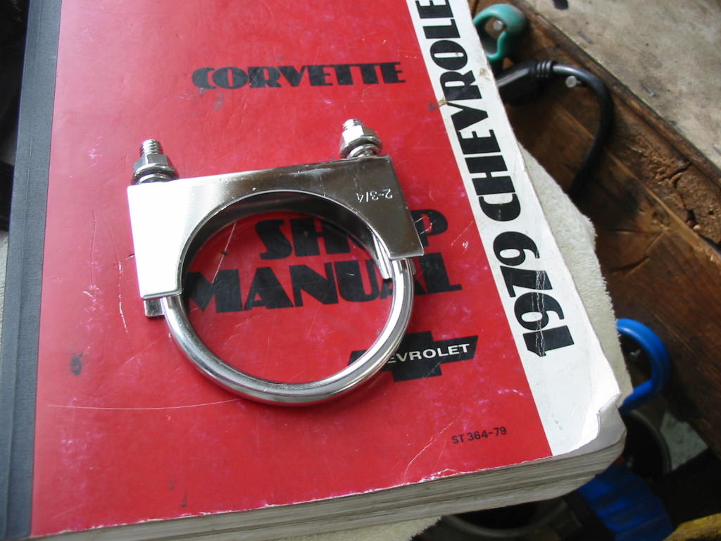
The 2-3/4″ stainless muffler clamps arrived from Amazon.
I needed these to keep the stainless adapter fitted tightly to the 2-1/2″ muffler pipe. All I need to do now is paint the short extensions between the adapter and the tail pipe with high heat black paint.
Next: hopefully the new condenser will be in tomorrow.
Tomorrow looks like an above zero day and good for startup. In the meantime…
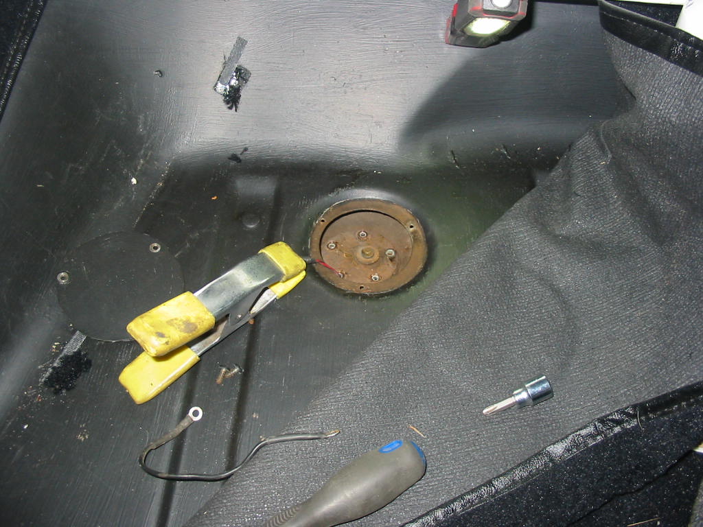
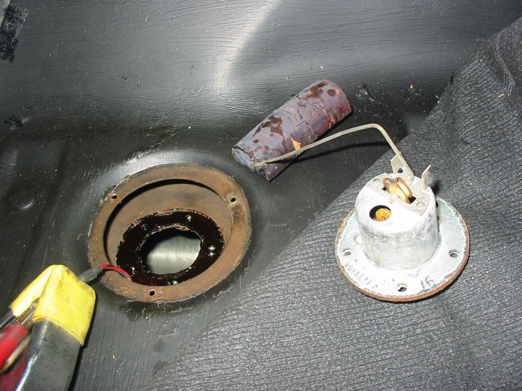
The gas gauge on the ’66 Commander is a bit wonky so I decided to pull the sensor and check it out. Not to hard to get at though a hole in the trunk floor. Studebaker used good steel in their cars. After over 60 years the screws came out very easily. Copper washers under each screw helped. The clamp is holding the sender connection so I won’t lose it between the tank and the underside of the trunk floor.
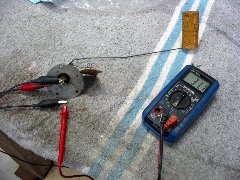
This is a new sender that I had in my stash of parts I saved from my Studebaker inventory that I parted with a couple of years back. It checked out OK, but when I connected it to the gauge in the dash it was OK on empty, but not on full.
This is the original sender. I ended up cleaning it out with electrical contact cleaner and compressed air. After that it registered empty and full OK on the dash gauge. Rather than try and scrape off the original gasket that is stuck to the tank I coated it with Permatex gasket sealant and reinstalled the sender. It would have been hard to get the old gasket scraped off without getting some crud in the tank. The part of the tank that is visible through the sender opening is nice a clean 🙂 The camera flash makes the metal on the sender look odd. It is also nice and clean. If the gauge still is wonky it might be that the cork float is saturated and not keeping to the top of the fuel. If it is I can swap the float with the one from the new sender that I have or buy a metal replacement.
Today is the day to start the engine and do the break in run.
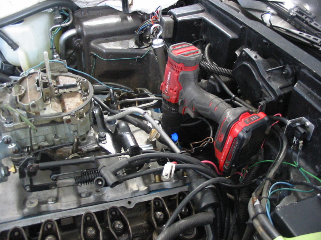
First step: using my drill on an oil pump spinner.
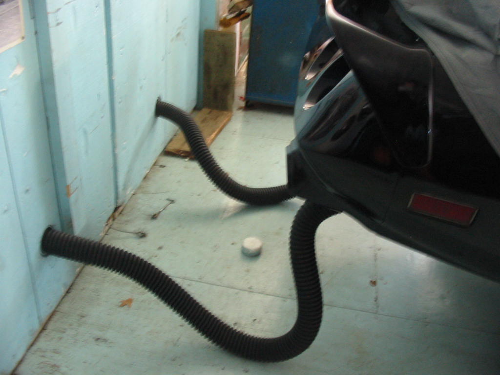
Next I attached the two exhaust pipes to the door outlets. I’ll use this for start up and when it’s going I”ll open the garage doors as there’ll be a lot of fumes. I have also opened windows and the trap door to the attic.
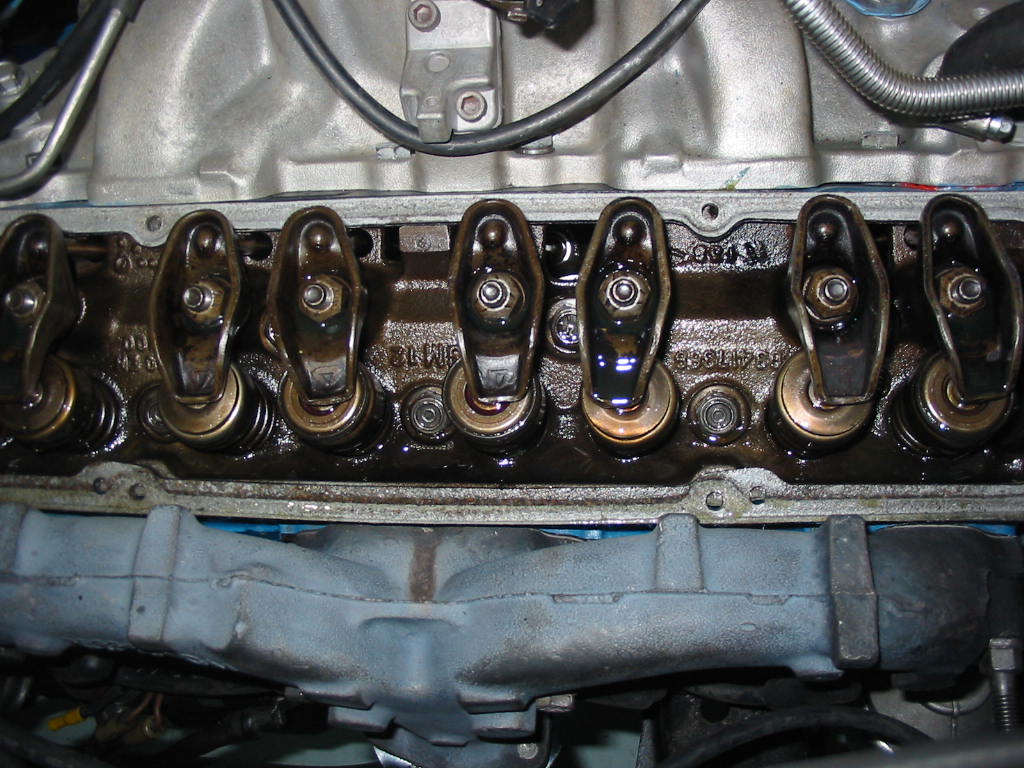
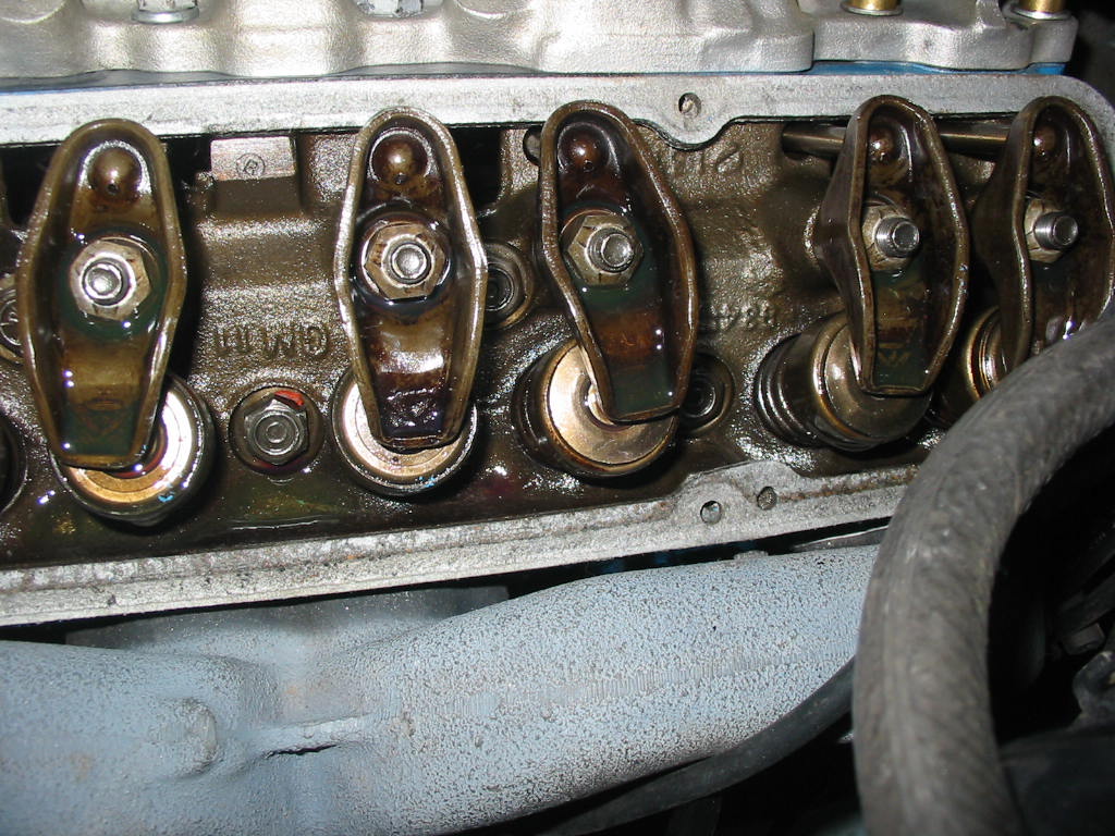
I ran the oil pump spinner until I got oil out of all the rockers. Didn’t take too long as the spinner created 40 lbs of oil pressure.
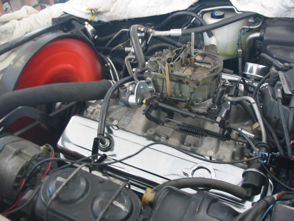
Hooray the engine started right up. No mixup with the wires or bad timing 🙂 I ran it for over 20 minutes between idle of 800 rpm and 1800 rpm. Two problems did crop up.
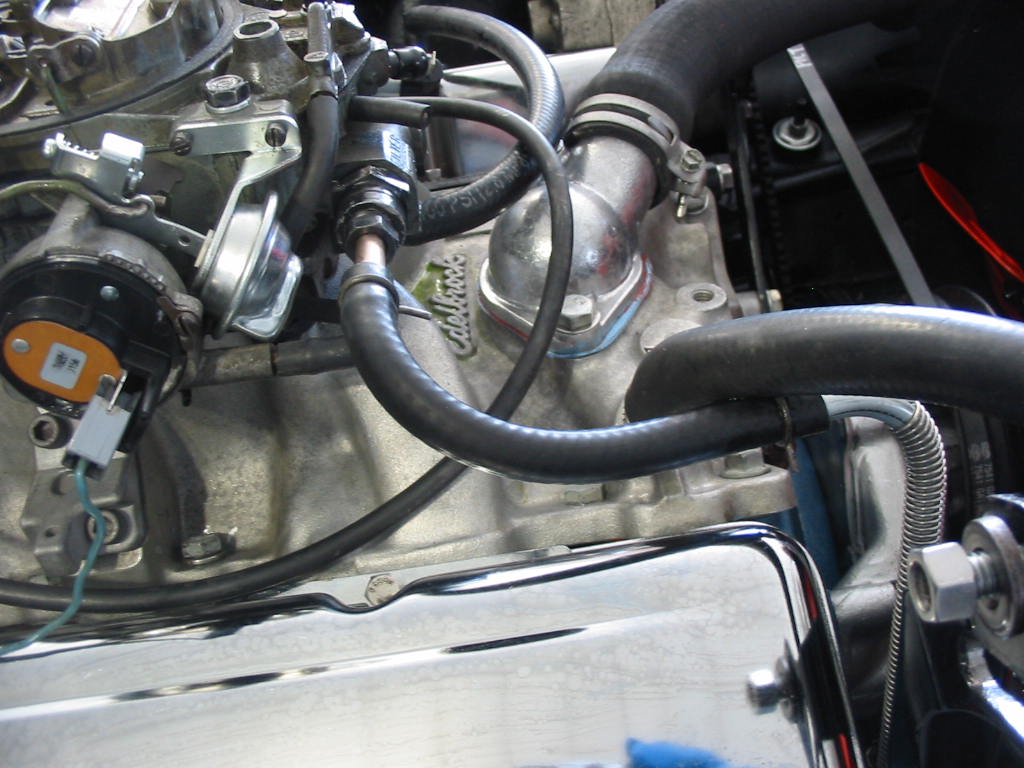
The fuel line at the carb leaked. I overtightened it and it still leaked. This is my $30+ nice new steel fuel line that I had to bend to fit and now I had to cut off the top of it and replace it.
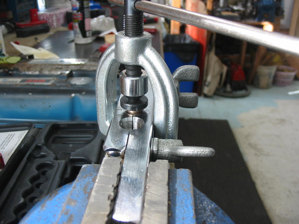
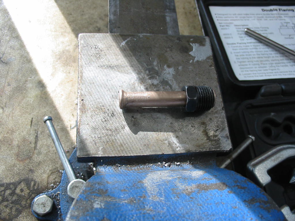
Fortunately I had a bit of copper/nickle fuel line of the right size with the proper end. I put it in the double flare tool and just started the first of the flaring process which gives a nice bubble on the end of the line to help sealing. I did it also to the end of the steel line I cut off. Now I only needed a couple of spring clamps to get a good seal. After this there was no leaks!
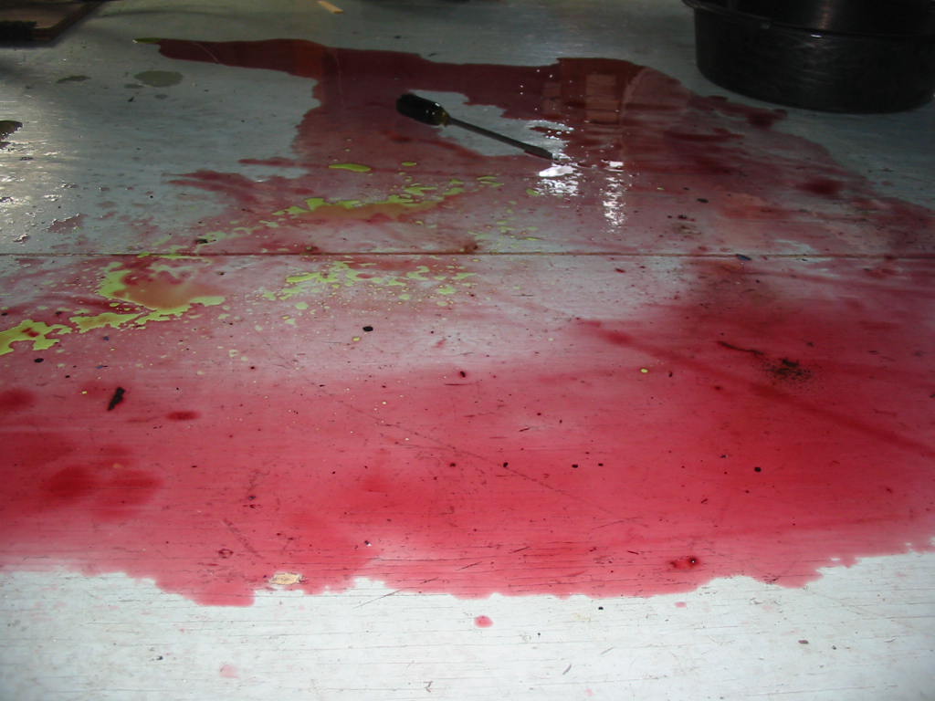
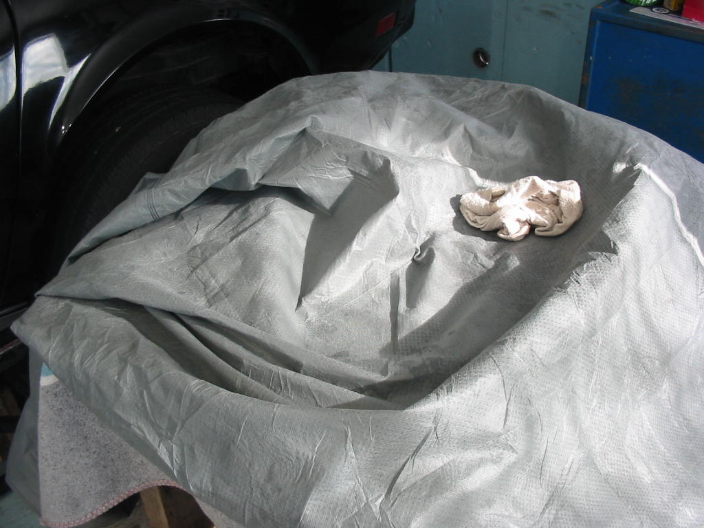
The second problem arose when I added oil to the trans to top it up. The trans was rebuilt so I couldn’t get all the oil needed on startup. Once I added enough oil it started to pump through the radiator cooling lines and unfortunately I did have the gear clamp on one of the lines tight. There is a bubble on the end of the line from the trans, but hot oil under pressure was just too much for the connection. It is right behind the fan so oil got sprayed everywhere even to the top of the windshield and over!
My car cover was piled on top of the car so it too got a smear of oil. Hopefully the sudsy rag got it out. If not I’ll take it to a laundromat and use an extra large washer to give it a going over.
Next: now I can go ahead with getting ready for the road.
Still below zero C. Waiting for warmer weather for the startup. In the meantime…
Getting the seat tracks back on with the newly painted adjuster knobs. The knobs are pull off/push on affairs.
A quick go-back to the hood. I forgot to glue on the new rear seal. I get a better glue spread using a small paint brush – it’s best if the glue is spread thin and even. I’m using Permatex adhesive because I have it. I prefer the 3M adhesive. It seems to stick better for some reason.
Back to the seats. I tried using contact cement to stick the carpeting onto the back of the seats, but it dissolved the paint on the seat back. I went looking for some contact cement that would work on carpets going on painted surfaces, but, no luck. I did find this LePage premium glue and decided to go with it even though I had to somehow keep the carpet squished onto the glue. The instructions say to put the glue on one side only and that it would take 24 hours to set. I rigged up this setup to keep some pressure on the carpet in the main areas of gluing – I put glue all around the edges of the carpet and a strip down the centre.
While waiting for glue to dry I’m cleaning up two stainless trim strips for the ’66 Studebaker that are attached to the rocker panels. I do like this Autosol metal polish even though the last tube I bought cost over $8
The glue has set well and the carpet is firmly attached to the seat back 🙂 Now I’ll ditto the other seat frame. No news from the upholsterer on the seat cushions.
The rocker trim and rock guards all cleaned up and ready for the install. In the end I used a buffing wheel on a bench grinder motor and green compound to get a nice shine on these used parts. I added a coat of Turtle was to keep them shiny.
In place and ready for the driving season.
Next: gas tank sending unit and gas gauge testing on the Stude.
I used my brake bleeder setup to prime the fuel pump. The hand pump couldn’t get the gas up so I connected my AC vacuum pump and the gas came up right away. This way the pump will only have to fill the carb on startup. All’s good???
I came back next morning to find a huge puddle of gas under the car. Turns out the return line corroded through and broke just behind the connecting flex line. Not sure why it didn’t show right away, but I’m glad it did now and not when I’m trying the break the motor in or later going down the road. I had to move the return line from under the feed line and cut off about 1″ of pipe along with the bubble at the end. I put on a new rubber pipe and used a high pressure clamp to hold it to the line – I sanded down the line for a better connection.
New left side power window motor to install. The window was dropping too quickly and not making it to the top.
Following the instructions I wound the window to the top (with the door open – it wouldn’t go to the top with the door closed) and held it in place with pieces of rubber tubing. I then removed the cam channel and all the regulator and motor mounting screws – the original rivets had been removed in the past. Next I was supposed to be able to slide the the top rollers off the upper channel – not possible! The rollers can’t get past the mounting studs at either end. So detach the channel from the window bottom frame, remove it and then the regulator and motor cam out. Doing all this friggin’ and jiggin’ caused the window to slip down a number of times The manual suggested using fabric tape to hold the window up. This might work, but whatever the paint is on the car it is soft and I didn’t want it peeling off with the tape!
Old motor and regulator. I’ve put in a bolt and nut to secure the regulator in position while I swap the motors.
I’ve got the motor in place with a generous amount of Lubriplate on the gears an bushing and a bit on the regulator gear plate. I’ve also added a bit of chain lube to the rollers. I like it since it flow in nice and then stiffens and stays in place. I also use some on the roller channels.
After I got it all back in it still doesn’t want to lower slowly and it still won’t go to the top with the door closed – bummer. I think maybe a new spring will help with the fast lowering, but I’m not sure about the window going to the top. In time the new door rubbers may compress some and help with getting the window to the top. I’ve tried adjusting the door out, but that didn’t help all that much. I think the real problem is that the aftermarket door rubbers just aren’t close enough to the original dimensions.
Next it’s time to get the hood ready for re-installation. I previously removed the sound deadening mat attaching thingys before doing a repaint. Here I”m making patterns for the back corners. I’ll do the same for the front corners.
Before I try to stick the new sound deadening materials I cleaned it all with Spray 9 and then with Windex just to be sure all the oils were off.
I decided to use what I have to do the job. Some thick matting and some thinner butyl. The thinner butyl matting had the manufacturer name plastered all over it. I don’t want to be a billboard for the maker so I removed the black writing. I used Circa 1859 household paint remover. It’s an eco-friendly product so not a lot of fumes while using it.
Next: still waiting for a warmer day to get the engine started – minus 22 this morning, brrrrrr!
I really couldn’t bend 3/8″ pipe to make a nice line from the fuel pump to the carb. So I sprung for a custom pipe ($43). I don’t know what shape of fuel pump that this pipe is supposed to fit, but it doesn’t fit my 350! The lead to the carb is fine, but the lead going to the fuel pump isn’t even close. So more bending needed. Thankfully there is a spring cover which should help me get it bent to fit.
I don’t know what it is about aftermarket parts for Corvettes, but it seems they all sorta just about fit. I had to do some bending and twisting on the 3/8″ line to the carb and the ‘S’ formed hose between the main gas line on the frame and the pump barely fit. It just went on the end of the pump. The nicest fit was the return line using open stock 1/4″ line.
Ran into a bit of a head-scratcher here. For some reason the new nicely painted fan wouldn’t fit inside the shroud. The fan blades were tight against the top of the shroud and I couldn’t get the lower clips in place or the upper support screws. At first I thought that I had mixed up fans with the 305 Caprice unit., but after some thought I did figure it out.
The left engine mount was sitting on top of the frame bracket. The bolt slipped in easily so in the dim light I figured all was OK!
With the engine properly seated the shroud fits nicely and the fan spins freely 🙂
Torque converter bolted to the flex plate and the cover in place. I won’t attach the driveshaft until the engine is successfully broken in. I’ll just put the yoke in the trans rear to keep the oil in.
Trans lines in place. The small 1/2″ crows foot on a 3/8″ drive is perfect for tightening the lines to the trans.
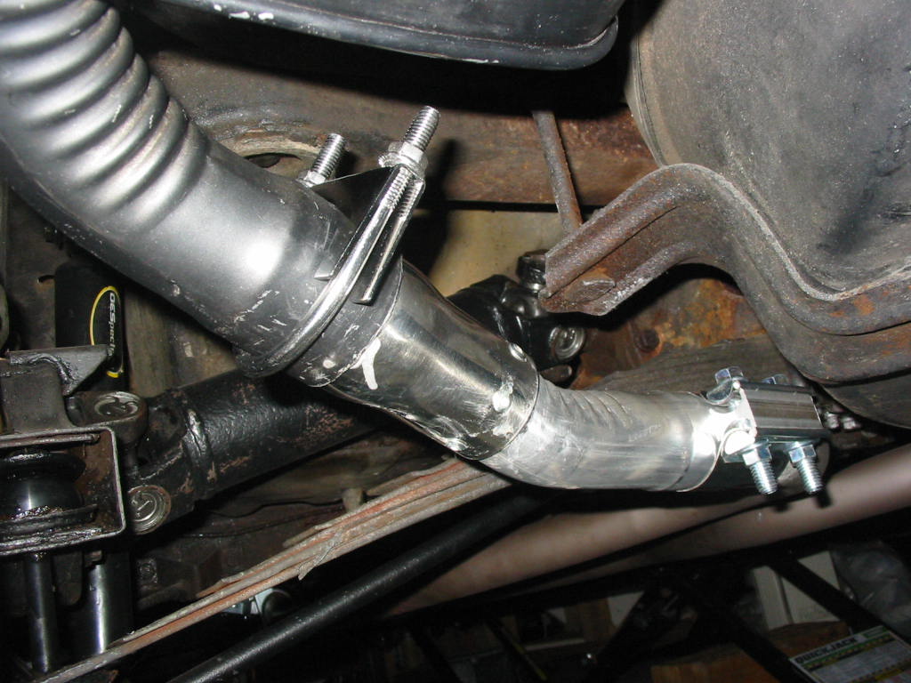
The chrome fitting at the end of the muffler is a 1-1/2″ OD to a 2″ ID adapter. After that is a 20 degree bent 2″ extension to join to the true dual exhaust pipe. Without them there is no way to connect to the muffler. Another case of aftermarket items needing work to fit the car. In this case quite frustrating since I paid $500 for the 4 true dual pipes – a lot of money for something that doesn’t fit out of the box and they aren’t even stainless!
My welding skills are horrible so I opted to use 5 pop rivets to hold the raw steel extension to the chromed adapter.
With the band clamps in place, the exhaust snugged up to the exhaust manifold and the crossmember bracket the whole exhaust line holds nicely in place.
Darn hard to get both mufflers to lie in the same position. In my case the back of the left muffler lies lower than the right. It makes a bit of a difference in the position of the tail pipe, but that shouldn’t be noticeable across the street on a dark night 😉
2″ true duals in place. I figure they provide about 23% more capacity than the original single 2-1/2″ centre pipe. The two band clamps are ahead of the crossmember and the support brackets are at the back of it.
Lastly I torqued the exhaust bracket clamp studs to 25 ‘# Some folks say it should be as high as 60’#. That’s way crazy for a 3/8″ stud and brass nut. If I sense any leakage I can snug them up a bit more if necessary – using new doughnut rings that should not be a problem.
Next: it’s 18 below zero right now and we’re expecting cold temperatures for the next week. I’ll need to have the garage door opened when I start and break in the engine. So I’ll be waiting for a warmer day to do that job.
If I have to do another engine install I’ll put the spark plug shields in place first. The left shield wasn’t too bad, but the right shield was a pain to fit behind the starter. The starter support strap had to be removed which allowed the shield to be squeeeezed in. I thought that I would need to drop the starter which would have been another step backwards.
Connecting up the shift cable. Easy-peeezy. The rubber thingy is my answer to replacing the accordion shaped boot that covers the sliding parts of the cable. To get one you have to buy a whole cable which seems crazy when the original cable is fine. I used a short length of bicycle inner tube and a couple of zip ties. Works just fine.
Putting the original exhaust manifolds in place. I like the exhaust gaskets supplied by Mahle in their engine gasket set. They have ears on each end so the can be slipped over the bolts easily with the manifold just off the head.
Ready to paint the fan blades. I’m going with Chevy orange which should brighten things up a bit and also stand out when the engine is running.
Exhaust and mid pipes test installed. I need to wait for my mufflers to dry before I can continue with the exhaust fitting. So far so good.
Looking a lot better with a coat of Dupli-color semi-gloss black engine enamel.
Hard to see, but I’ve put a thin coat of Permatex sealant around each of the openings in the carb gasket – both sides. This gasket was new when I installed the carb on the 305 engine so not much use. I want to be sure I don’t get air leakage at this point.
Carb in place and trans TV cable attached. I forgot I had to attach the TV cable before its bracket is in place so had to take a step back. The bracket is attached to the back two intake bolts that I have been extended up about 1″ with brass sleeves so that the TV and throttle cables are pulling straight.