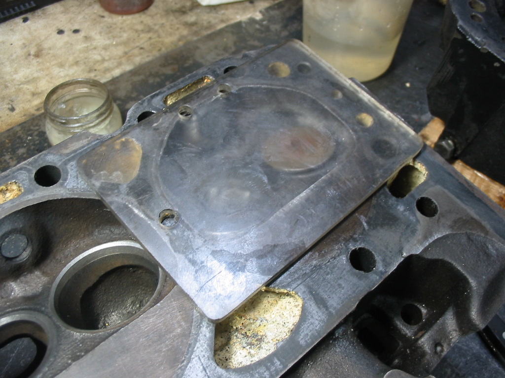
A little rig I made up to check the piston to deck clearance. Not exact, but close enough. I got a measurement of .047. With a beaded steel gasket with a compressed thickness of .015 I’m looking at a quench of .062. Not a good number for a performance engine. The original engine had a deck height of .042 and a compressed head gasket of .015 so a quench of .057, but that was with dished pistons and I’m using flat top pistons. If GM was happy with that then I should be OK.
I don’t have the special tool to push the oil pickup tube into the oil pump. I used a brass punch, small maul and lots of oil. Worked OK I twisted the pick up down a bit.
I installed a new oil pump extension rod with a metal collar before installing the new standard oil pump.
I installed the oil pump and then put the pan in place to check and see if I had twisted the pickup down too much. Turns out I did and it held the pan up off the block. I just twisted the pickup up a bit and the pan fit properly.
Time for the cam’s timing chain to be installed. I’m using the harmonic balancer installation tool with a metal spacer to push the sprocket on to the crank.
This is a Cloyes timing chain kit. The crank sprocket can be installed in three different locations for 2 deg advance, factory fit and 2 deg retard. I have put it on the factory fit for the first test of the cam timing.
Timing marks lined up. As you can see it is a double roller setup. I think I went overboard on this as the engine won’t be raced or driven extra hard. A standard quality single roller would have been fine.
First step in degreeing the cam is to install a degree wheel and static pointer.
First step is to measure the new piston clearance. They are tight on .002 so I’m thinking maybe .0015 or maybe .001. Good to go as they say.
I used the piston to push each of the two top rings in the bore to check the ring spacing. They are in the range according to the instructions with the rings – Minimum of .016, actual .020 (which is below the .027 max in the service manual)
Rings on the piston. I used my fingers to get the oil rings in place and a set of piston ring expanders to help get the first two on. I’ve rotated them according to the manual – top ring at the top, second at the bottom, oil expander at the top and the oil scrapers at 4 and 8 o’clock.
I’m coating the rings and the cylinder wall will some fresh engine oil before putting the piston in the ring compressor. I have short bits of rubber hose over the rod studs to protect the crank when the piston is pushed home.
I’ve tightened the compressor then pushed the piston out until the skirts are just showing. That helps position the piston before tapping it into the bore.
Number 1 and 2 pistons in place with a bit of plastigage on each. I’ve squeezed in a feeler gauge between the rods to stop distortion when I torqued the cap nuts. The clearance was about .016 which is a bit higher than the service manual, but less than the .025 limit other 350 references indicate.
Plastigage showing about .0015 which is way below the service manual list of .0013 to .0035.
A liberal amount of assembly lube before putting the caps back on and giving them a final torquing to 45#’
On to balancing the pistons. Unfortunately I wasn’t able to balance the pistons and rods separately. I had to send them out for the rods to be removed from the original pistons and the the new pistons ‘hung’ on the rods. I didn’t want to mess with them and ruin a piston in the process.
I did weight all the pistons before they went to R&D to be hung on the original rods. This won’t be a professional balance by any means, but at least the pistons will be about the same weight and the piston/rod weight will be also about the same. I’ve sealed off the wrist pins as best I can to prevent any fine filings from lodging between the piston and its pin.
The recommended p rocedure is to remove metal from the pin bosses. With the pins in place I didn’t want to grind near them so I removed what I needed from the outside bottom surface and any adjoining casting ridges.
Once the piston difference was evened out I removed the remaining weight from the total piston/rod combination from the metal blob on the end rod cap. For example if the total weight was 1309 grams which was 7 grams heavier than the lightest piston/rod weight and the piston was 3 grams heavier than the lightest piston I first removed the 3 grams from the piston and then took the remaining 4 grams from the the rod cap.
After a couple of hours I had them all done. They all are now about 1302 grams each. My scale only goes to rounded grams. I could have done better with a scale that showed a couple of decimals. Even so this should help the engine run smoother.
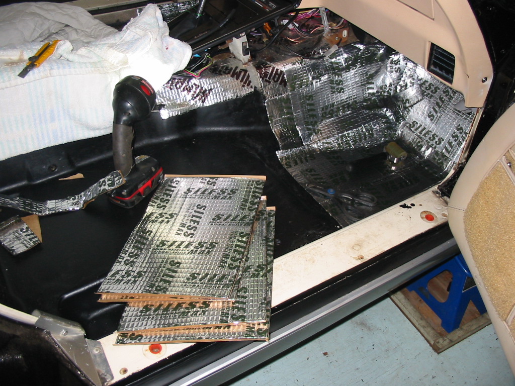
The new box of Siless sound deadener has arrived so time to finish the floors.
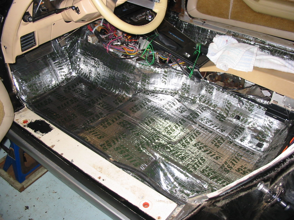
All covered. I wasn’t too worried about overlap. I figured that it just added to the insulation and the extra thickness shouldn’t affect the carpet as the the foam I removed was way thicker. I kept the foam just in case I need to use it if the carpets don’t lie right. I’m thinking that maybe the foam (1/2″) was there to replace the original factory padding which is usually a thick felt padding. The car, I believe, was left outdoors for some time in the past and it leaked. Damaging the metal under the shift mechanism on the trans hump and likely on the foot wells as well.
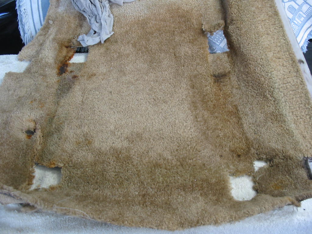
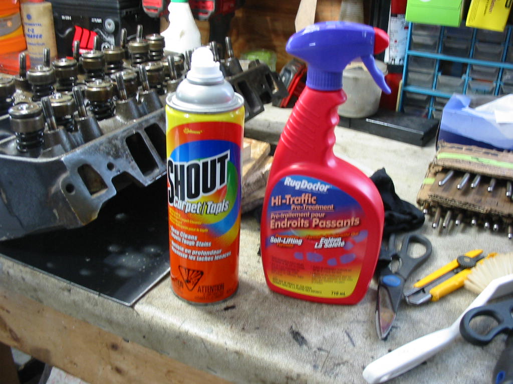
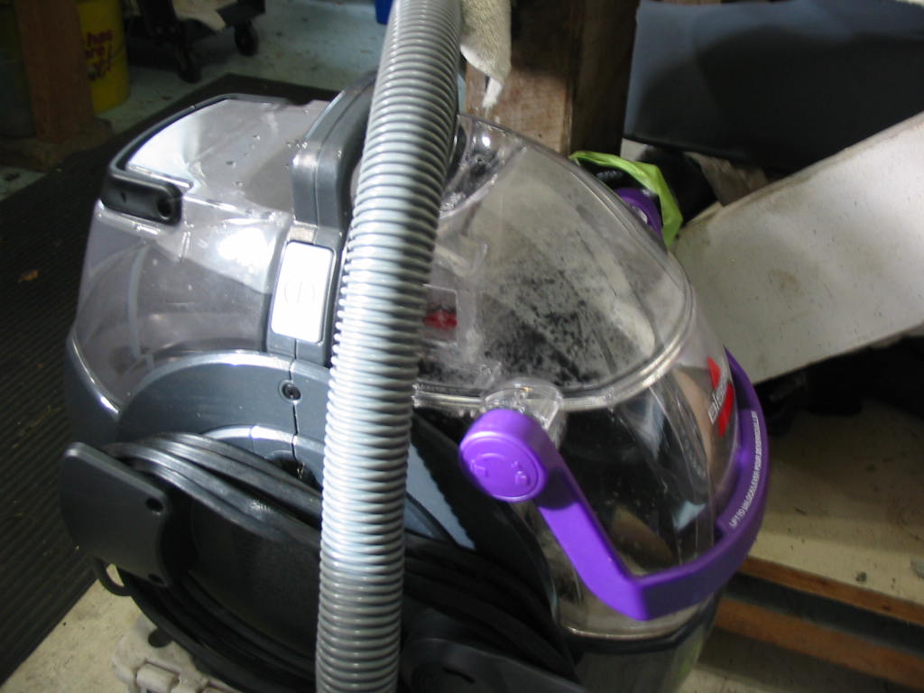
With the carpets out of the car it is a good time to give them a vigorous cleaning. I’m using foam and spot spot spray as well as a Bissel rug cleaner with hot water to suck out the dirt of years.
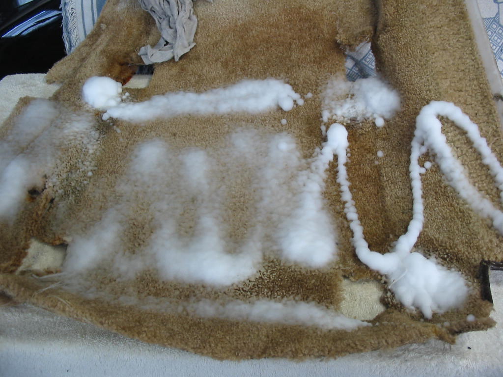
Lots of foam and then I rubbed it with a sponge until it disappeared into the carpet nap.
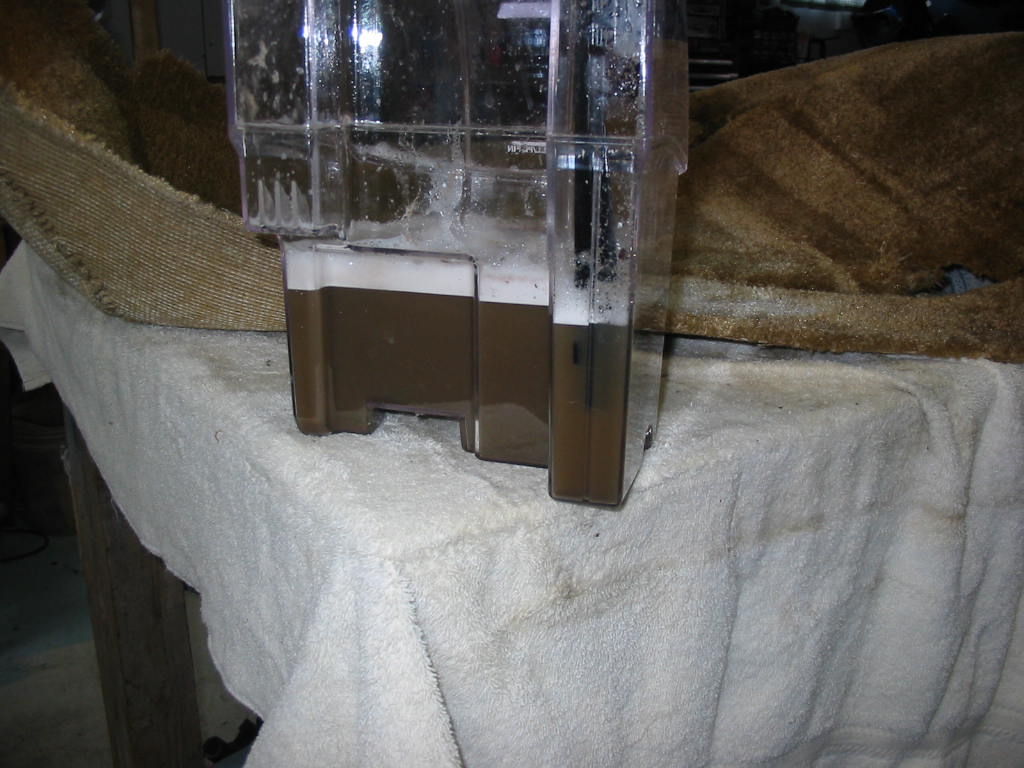
The Bissel cleaner removed lots of dirt – even more came out in an earlier cleaning of the rear carpeting.
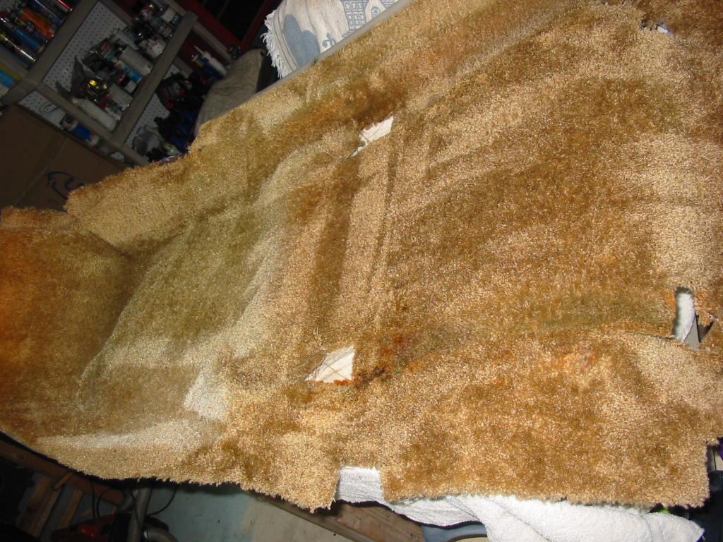
All clean. The area to the right that is under the seat shows more of the original colour. The area to the left in the foot well bottom has lightened up over the years. Not a problem as I have carpet mats in that area.
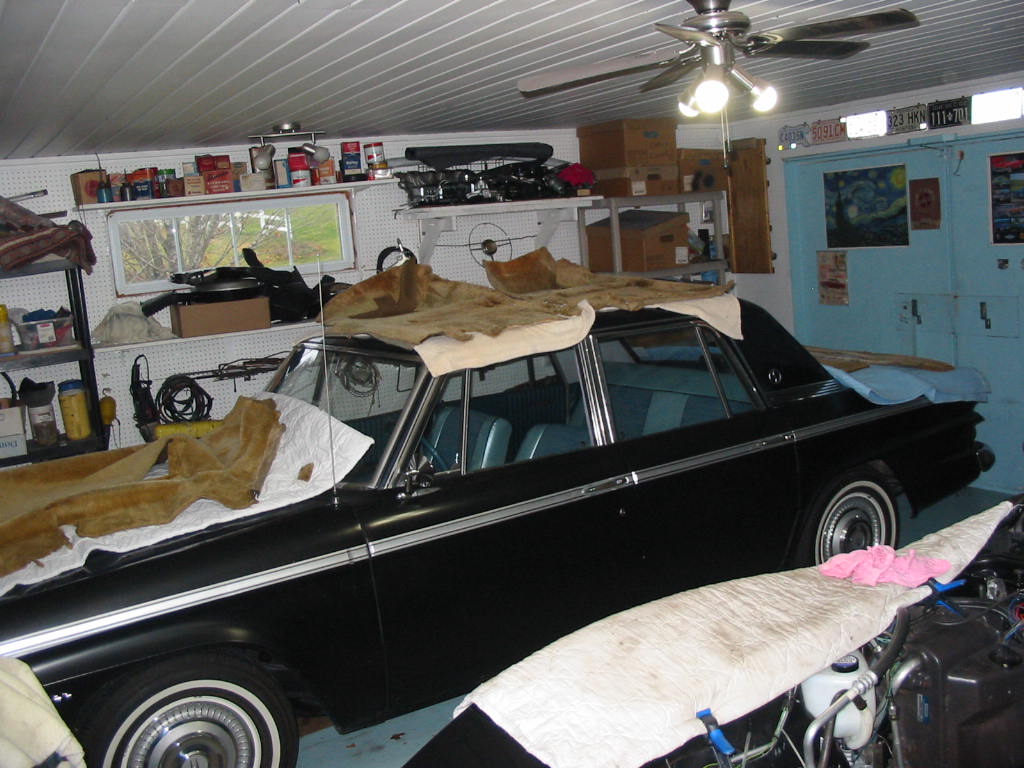
The Studebaker has become a temporary drying rack. I’ll leave them for a few days to be sure they are totally dry before doing the install.
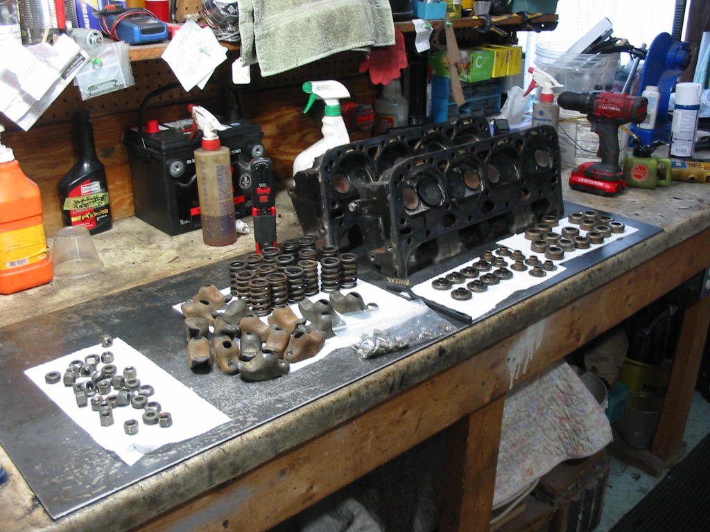
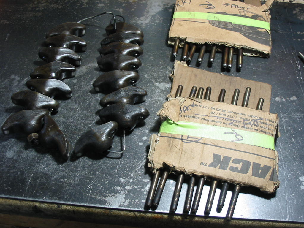
Everything cleaned up and ready for the install. Except for the rockers, balls and nuts. I’ve decided to try and keep things together that were in the original 350.
Still to be cleaned. The rockers, rocker balls and push rods will go back in the engine as they were originally. There shouldn’t be a whole lot of mismatch between the old push rods and the new lifters – but likely some so a little extra wear there over time while they seat together.
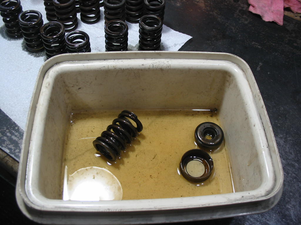
Giving the parts a coat of engine oil before assembly.
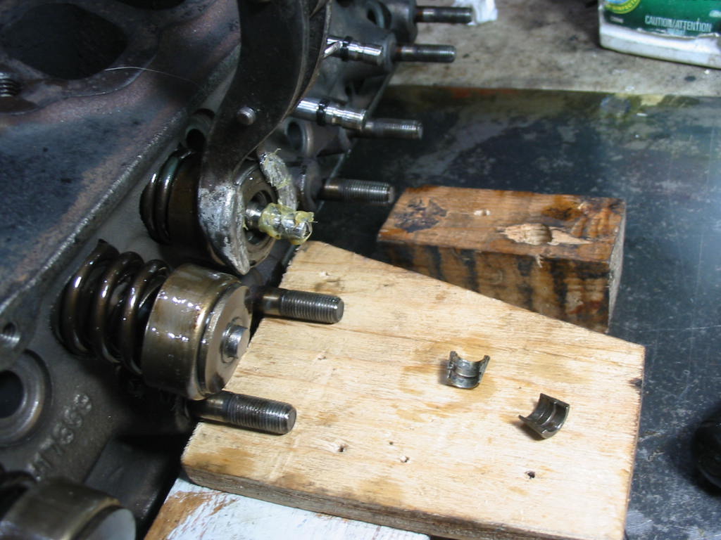
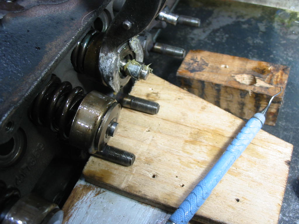
The valve spring compressor is holding the spring back, but at an angle so I can barely get the seals in place. In some cases I had to put wooden wedges between the valves to get the compressor to move over. A little wheel bearing grease on the stems to hold the keys in place.
Some times I had to lean on the spring compressor when releasing it and it was hard to do it slowly. If I had to do it again I’d buy one of those compressors that attach to the rocker arm studs. They seem to compress evenly and also the long arm should make it easier to release slowly so the seal doesn’t get damaged
To try and make sure the seals are in place OK I have put a few drops of clean parts cleaning fluid around the top of each valve stem. If it’s going to leak the solvent should get through. Otherwise I have a chance that the seals are in place properly. If when I get it back on the road I find fouled plugs that will be a sign that an intake seal is not working and I’ll have to replace the seals with the heads on.
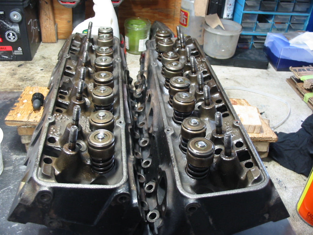
Heads ready to go back on the block. I’ll be doing some head scratching when i get the pistons back from R&D. I’ve got to figure out what I need for a head gasket. I’m trying to keep the compression ratio in the low 9s and have a quench close to .040.
Next: Now back to the interior while I wait on my pistons.
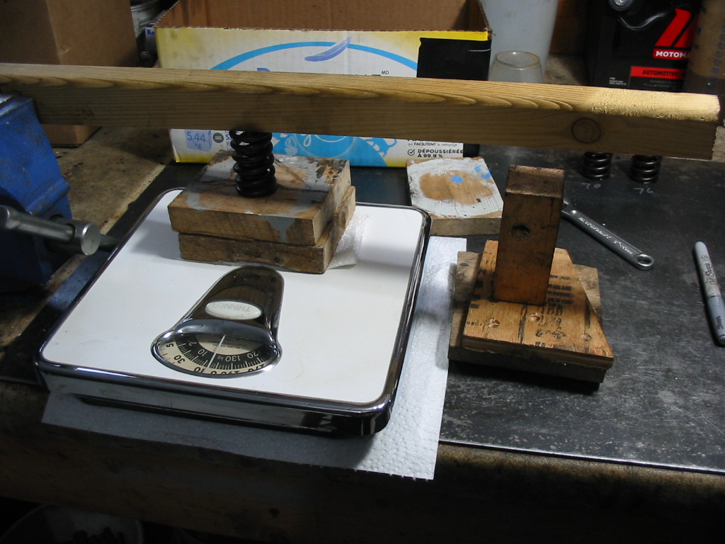
This is my gizmo to test valve spring strength. The arm is held in the vice with a bolt acting as the fulcrum. The block below the arm on the right limits the about of squeeze on the spring. The scales aren’t all that accurate, but I’m only interested in singling out the strongest. Each spring is placed in the same spot and the arm is centreed over the spring and it is compressed the same amount.
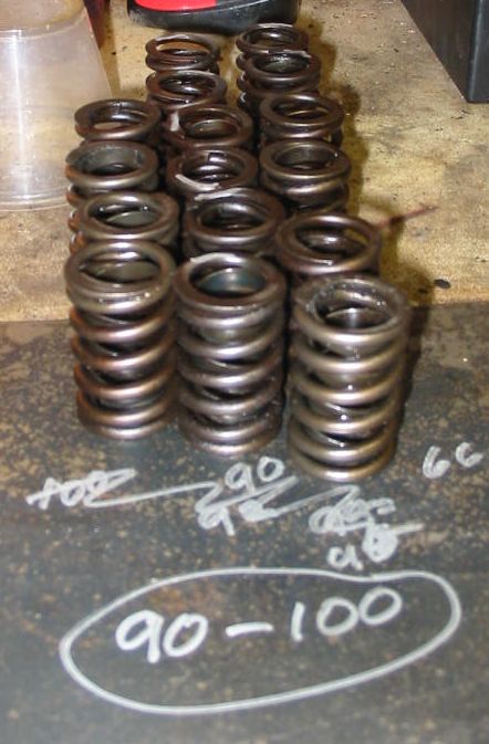
I tested the original Chevy springs as well as the ones from the crate engine. The range went between 66 and 100 lbs. 16 of them were in the 90-100 lb range and that’s what I’ll use in the engine. They will not be good for high revving, but I will likely only ever get to maybe 4000 and that in passing gear.
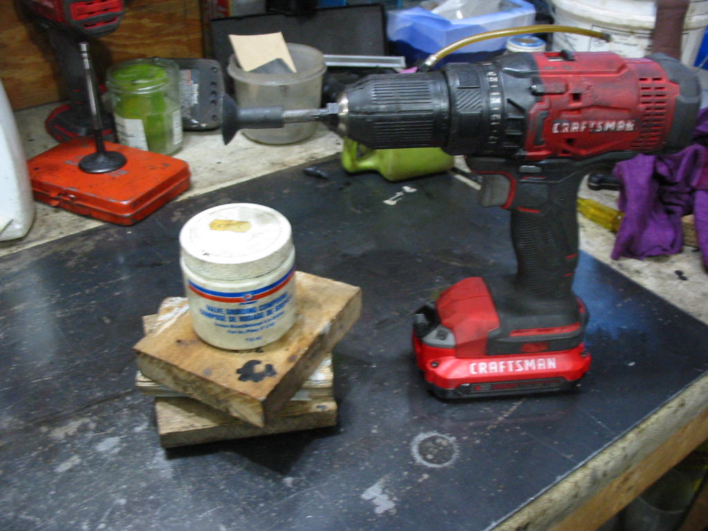
The next job to be done was lapping the valves. I used Permatex valve grinding compound and a lapping too adapted for my drill. I coated each valve and seat with the compound and then ran the drill forward and backward twice. Lifting the valve and setting it down 6 times each way with a bit of a delay between each lift to allow the compound to do its job. I only needed to do this routine once for each intake, but twice for each exhaust valve. The result was not perfect, but pretty darn good with next to no tiny pits showing on the valves. The seats all seem to be perfect.
Another trip to the parts washer for the heads and valves to remove all vestiges of the grinding compound – it’s pretty fine stuff and would mess up the valve guides if it remained in the heads. I was careful not to get it in the valve guides while I was doing the lapping.
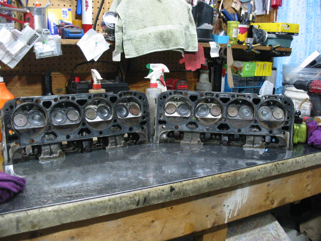
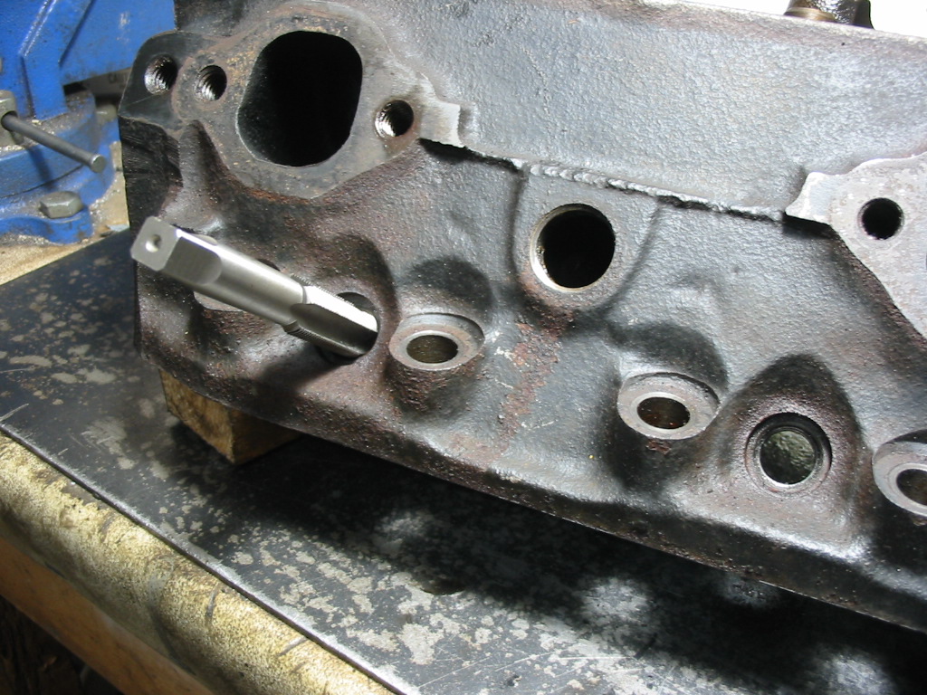
I’m exchanging the original crack prone heads from the L48 for a set from a GM crate motor #83417369. The Internet AI info about these heads is as follows-
“The GM 83417369 is a cast-iron cylinder head with a 76cc combustion chamber and 1.94-inch intake/1.50-inch exhaust valves. These were basic, non-performance heads from the “smog era” often found on Goodwrench crate motors. For a performance upgrade, they are often paired with an RV cam, a dual-plane intake manifold, and a 600-650 CFM carburetor to improve low-end torque. “
And that is about what I’m going to do with a Stage 1 cam, flat top pistons, high rise intake and the standard Qudrajet 4 bbl.
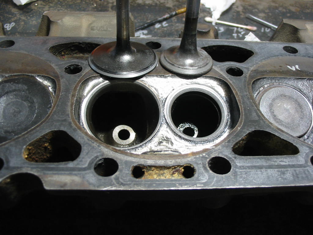
The valves and heads are in good shape so I can use them as is with a bit of work. First I’ll clean them up and then cc the combustion chambers to see how even they are. I’m not trying to do an expert blue printing job. I have done this in the past and feel that it is good to get the heads even and also same with the piston and rod weight. The closer I get the smoother the engine will run. The last engine I did this on was a Studebaker 259 R1 (stage one cam from factory) and the engine is very smooth with just a light lope at idle.
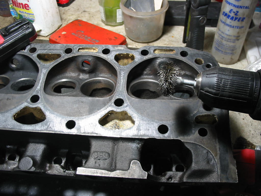
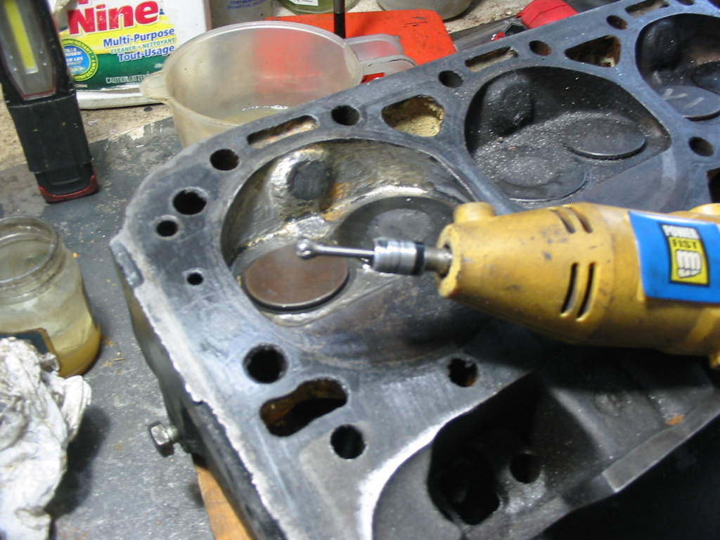
Here I’m cleaning up the combustion chambers with a brass wire wheel so as to not damage the valve contact surfaces. There wasn’t much carbon residue.
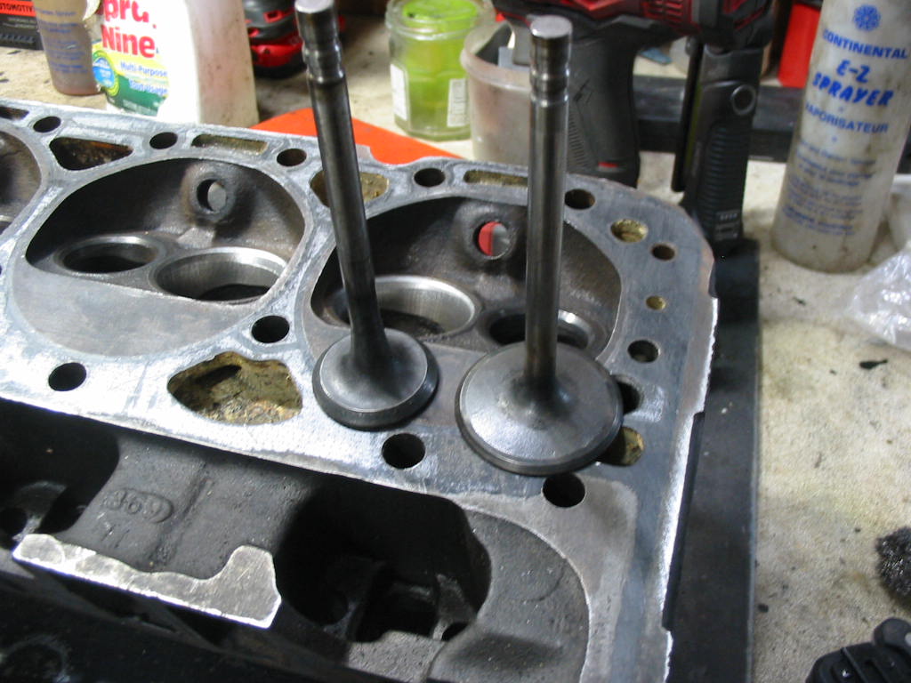
After cleaning the combustion chambers, including the valve openings, I cleaned up each of the valves on a wire wheel – being careful not to hit the valve/head contact surface. the exhaust valves were fairly clean, but the intakes had significant carbon deposits. May have been the result of poor valve seals on the intakes.
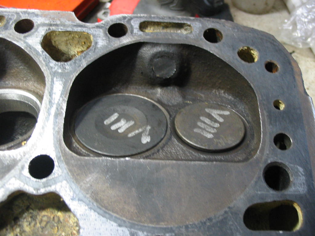
With the valves in place I went on to blocking the spark plug hole with a blob of dum-dum – carefully flattened to the head casting surface.
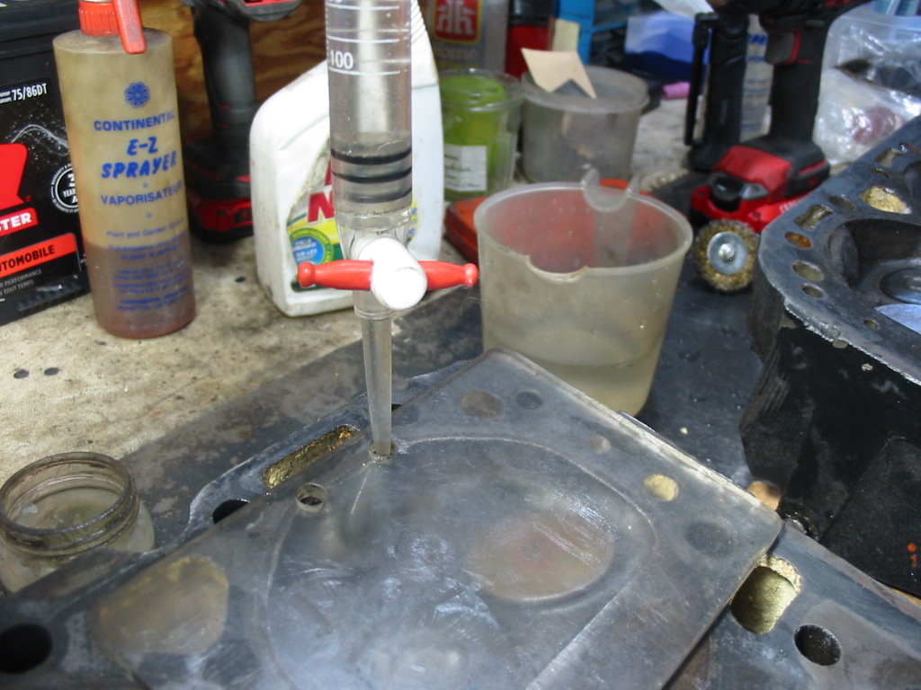
I used this plastic plate for earlier cc jobs – ignore the hole at the side. The two smaller holes at the top are the important ones. The head is tilted slightly so the to holes are a little up. The plate is sealed to the head with a smear of vaseline around the combustion chamber edge.
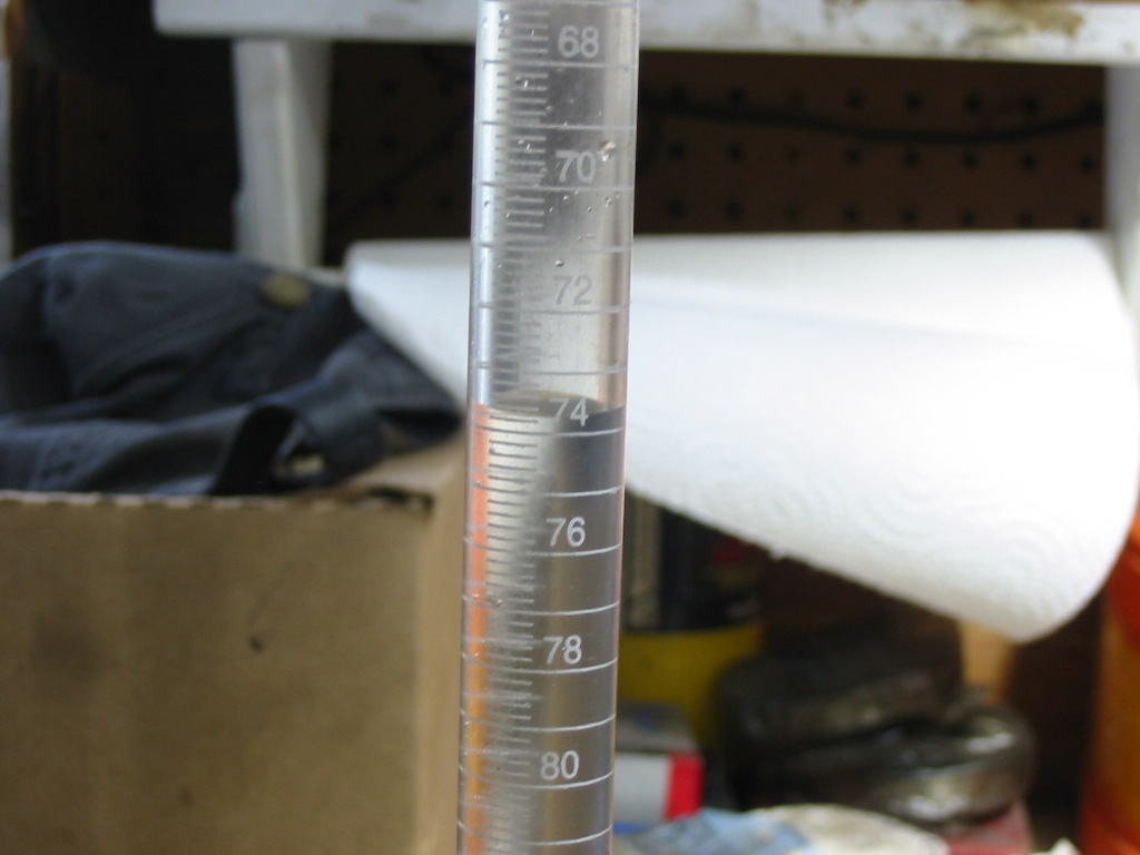
I picked up a pipette from Amazon some years back. It is marked off in ccs. I fill it to the top (0 cc) and then fill the combustion chamber. I fill it until the two holes are filled to the top and all the air is out of the chamber. I’m looking for an even combustion chamber volume. t The little extra water in the two fill holes will give me a slightly higher reading, but it will be the same for all cylinders. The final number may be a bit off, but they will all be the same and it’s the evenness that counts.
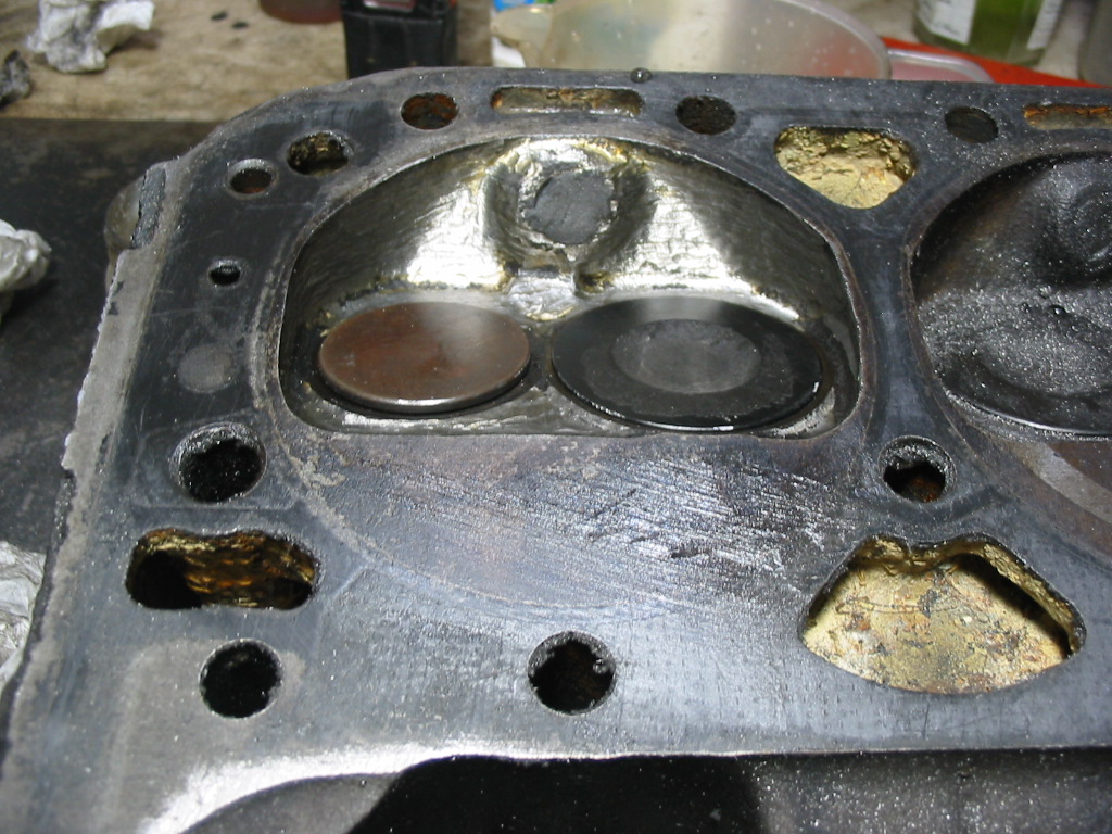
This particular cylinder is showing about 73.7cc The range of volumes is between 72.0 cc and 75.0cc. So I will need to open up all combustion chambers to about 75.0 ccs. From what I have read it’s best to get them within 1cc of the largest chamber. The heads are rated at 76cc.
There will be very little extra volume in the plug area so I’ll just go with 75 cc heads in my compression ration calculations. In truth it will be a fraction less because of the two holes in the plastic cover plate.
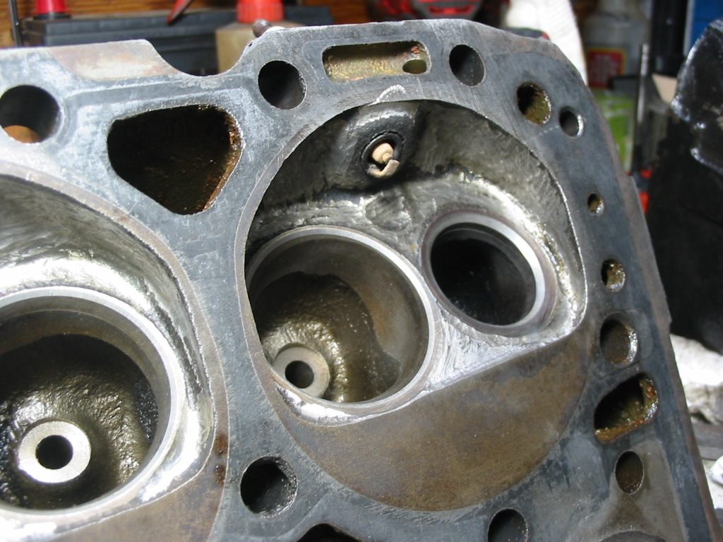
#2 cylinder was the smallest at 72.0cc. I used a small ball grinding bit on my dremel tool to scrape a small amount from the chamber surface and remove some of the shrouding around the valves. The amount removed from each cylinder varied. Final result was all cylinders within 1 cc of 75 cc.
Took a moment to clean out the plug holes after removing the dum-dum used to seal them off while I did the cc work.
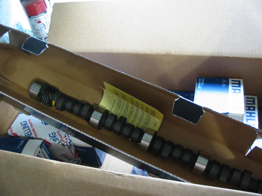
New Melling stage 1 cam and lifters have arrived. They should mimic the L82 in that department – ‘Excellent Low End Torque and Horsepower; Good Idle and Daily Usage’ is their claim.
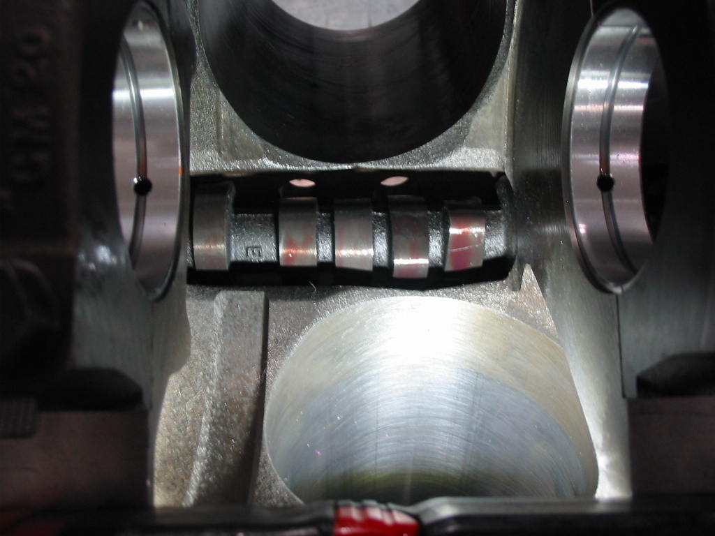
Cam in place with a generous coat of Melling assembly lube. I like the stuff if is thick and very sticky.
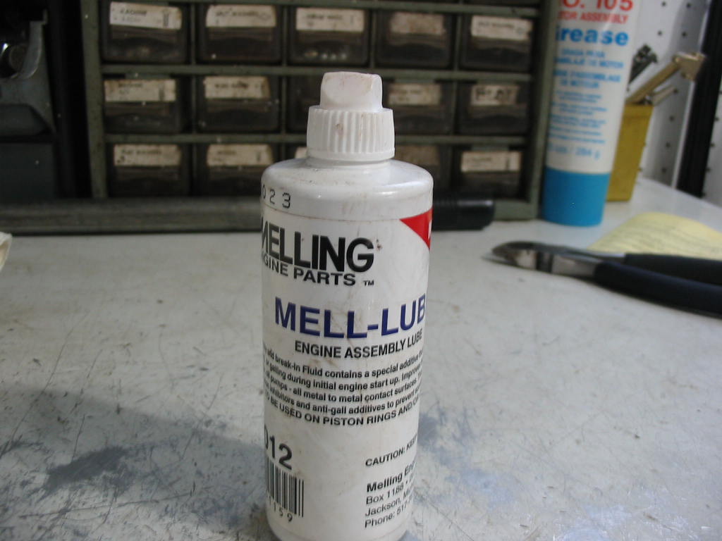
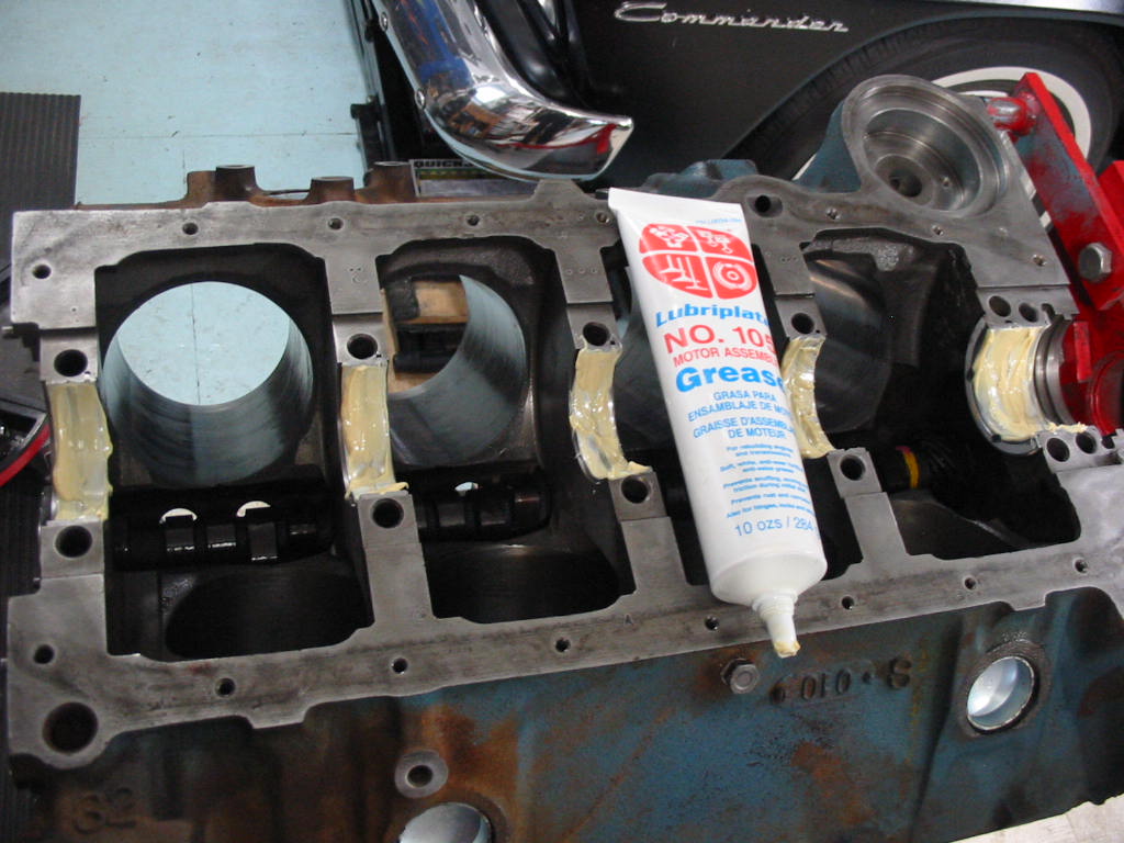
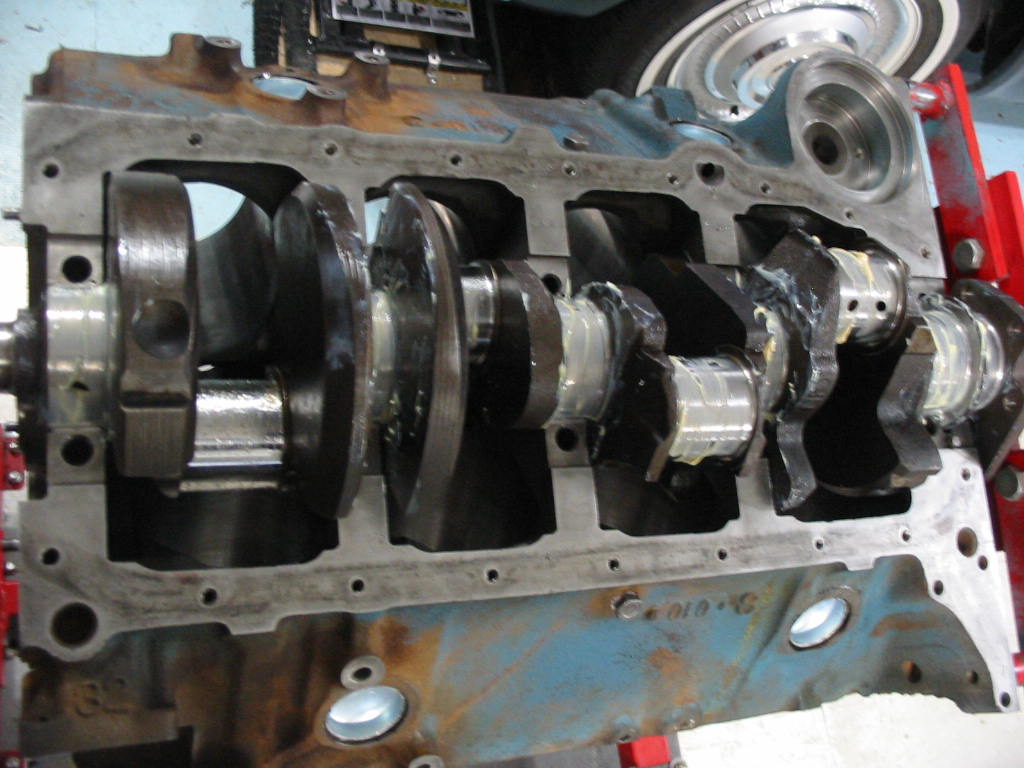
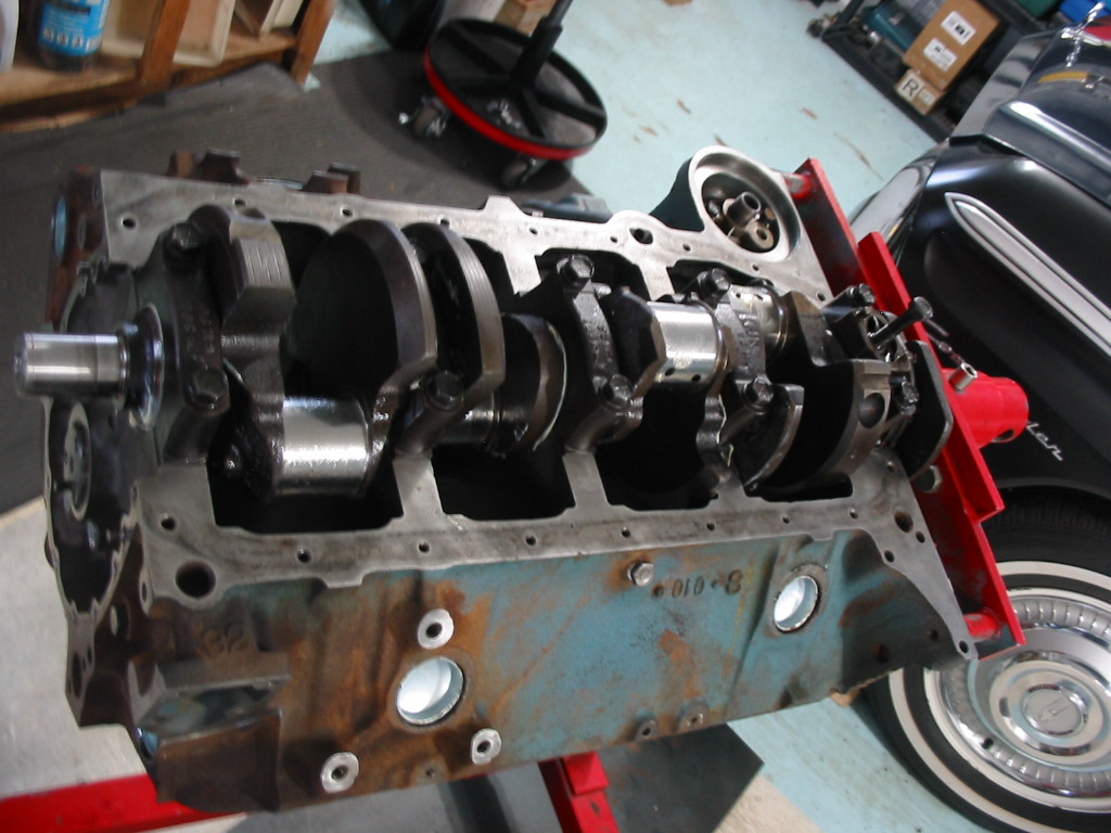
With the cam in place I’ll go ahead and put the crank in. I’m using Lubriplate No. 105 as my assembly lube for other than the cam and lifters.
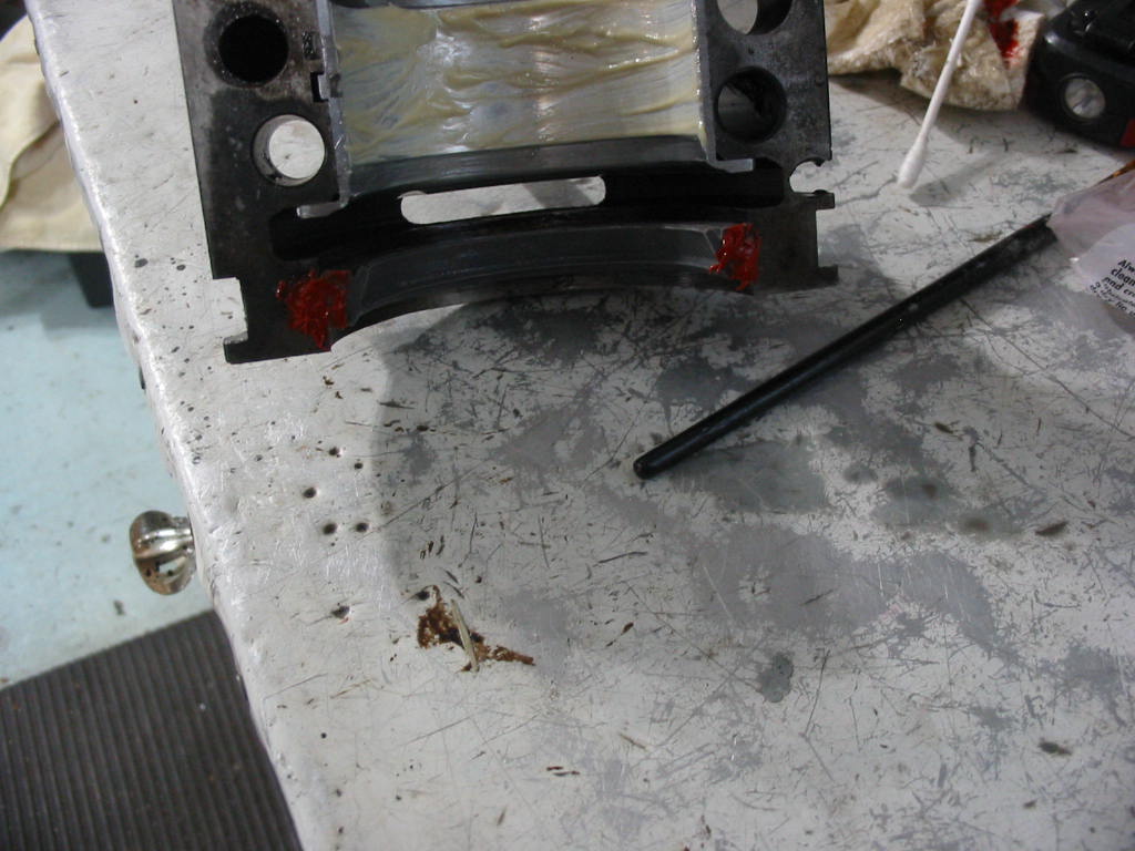
Following instructions that came with the rear seal, I’m adding a dab of red sealant to the ends.
Crank in place with a dab of red sealant on the ends of the rear seal. I may have overdone it a bit. Likely should have only put it on one side. Hopefully it won’t come back to bite me and I end up having to replace the seal with the engine in the car. I’ve done it before. Not too hard, just a bit messy and a bother.
Crank firmly in place with mains torqued to 80 ‘#
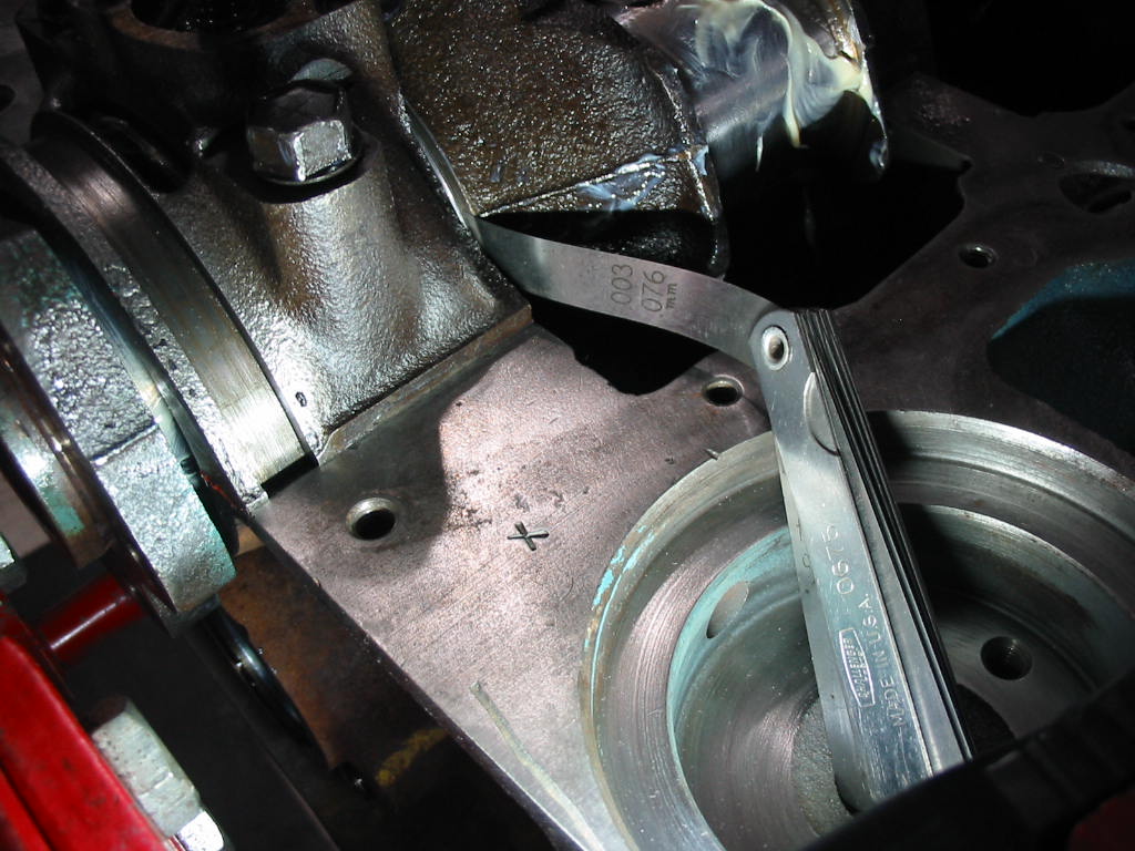
With the main caps in place it was time to check the crank end play. I moved the crank back and forth with a rubber dead blow hammer and then did the check. The clearance wasn’t even all the way around. I got measurements between 0.002 and 0.003 where I could get the feeler gauges in. So within spec of 0.002 and 0.006.
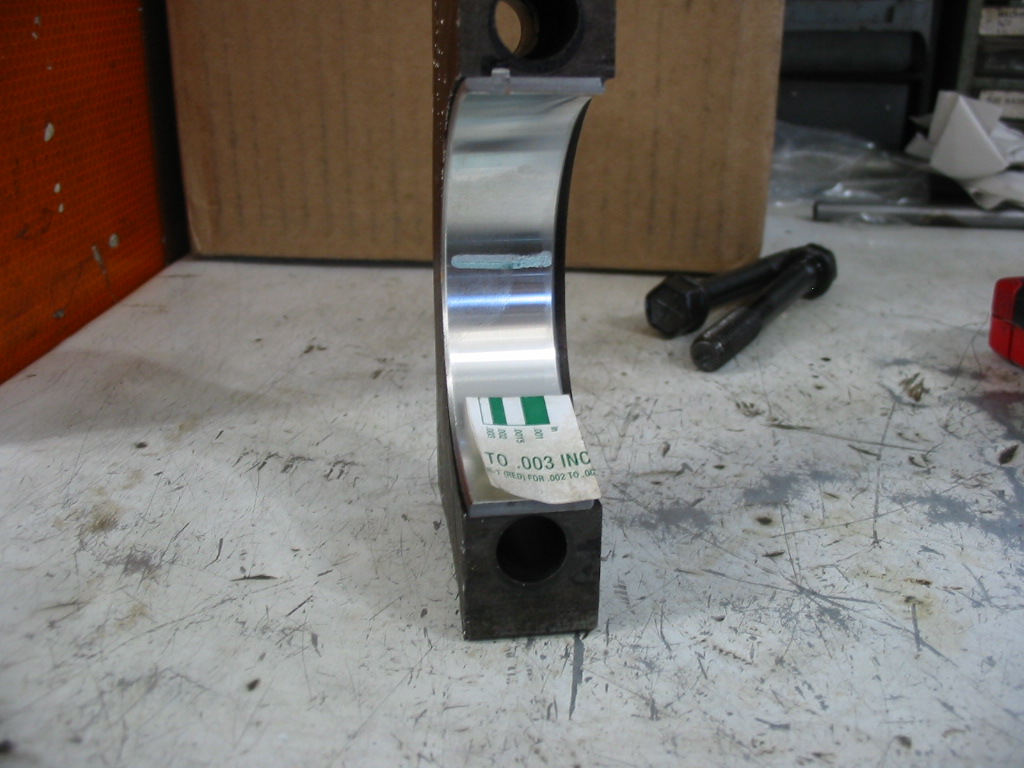
I wiped the mains before setting the crank in the block on new bearings.
I put a short strip of plastigage that can measure between 0.0015 and .003 on each main.
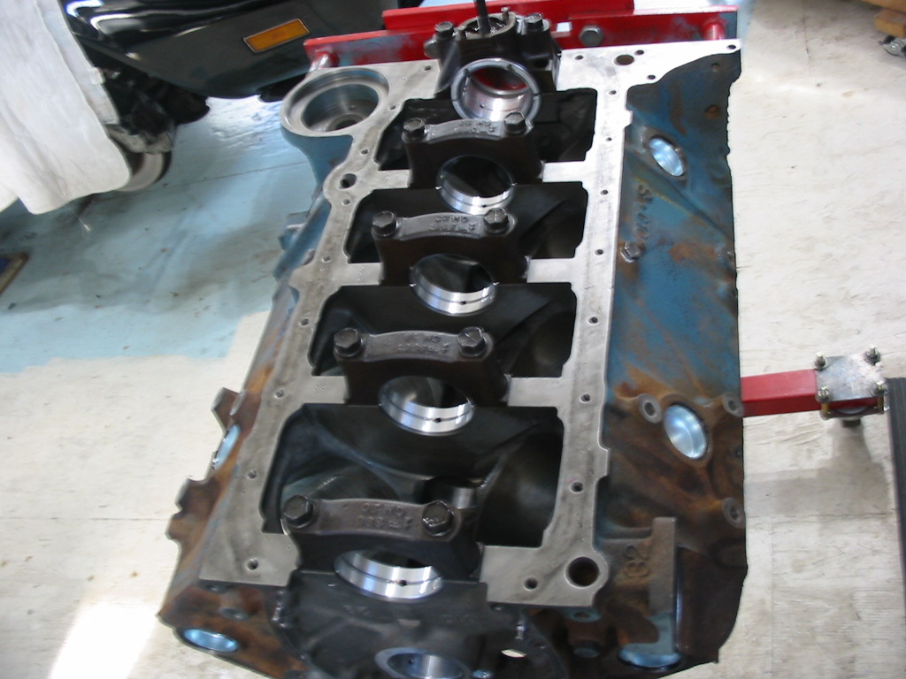
I then put all the main caps in place with the new bearings and torqued them all down to 80 ‘#. I measured each and I came up with between 0.0015 and 0.002 for numbers 1 – 4 and 0.003 for the rear main. So all withing GM spec 🙂
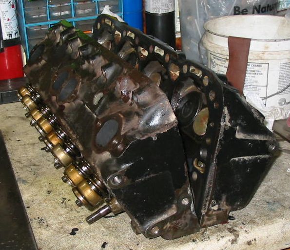
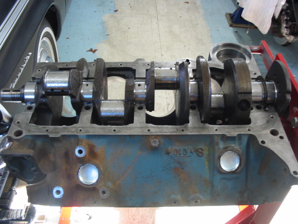
Main bearing caps in place. Best way to avoid damage to the new bearings. I’ll leave the crank out until the new cam arrives. It will help to have access to it from inside the block so the chances of bearing damage is minimal. So waiting on Rock Auto now.
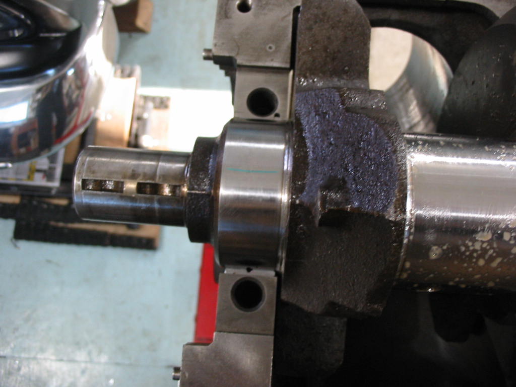
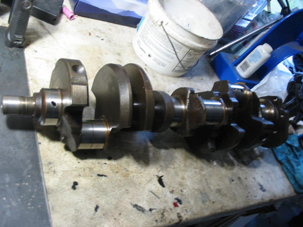
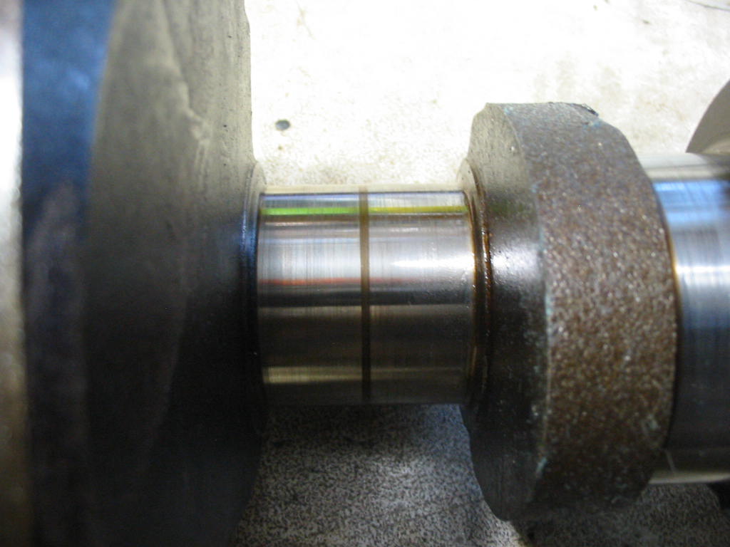
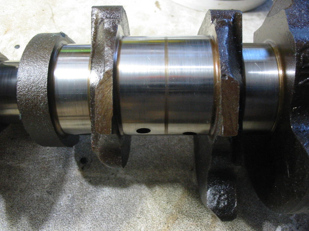
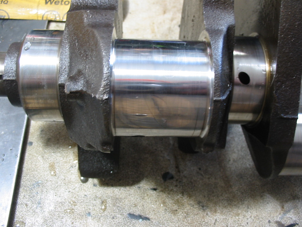
The mains and journals are showing minimal wear. The journals are at 2.1″ which is the original dimension and the mains are at 2.447 which is close enough to the original 2.448 for me to go with standard mains and journals.
Just a bit of sanding and polishing to clean the mains and journals. I’ve used 1000 wet paper followed by wet 1500 and then dry crocus cloth to clean them up a bit. This should do the job nicely for my DIY engine job.
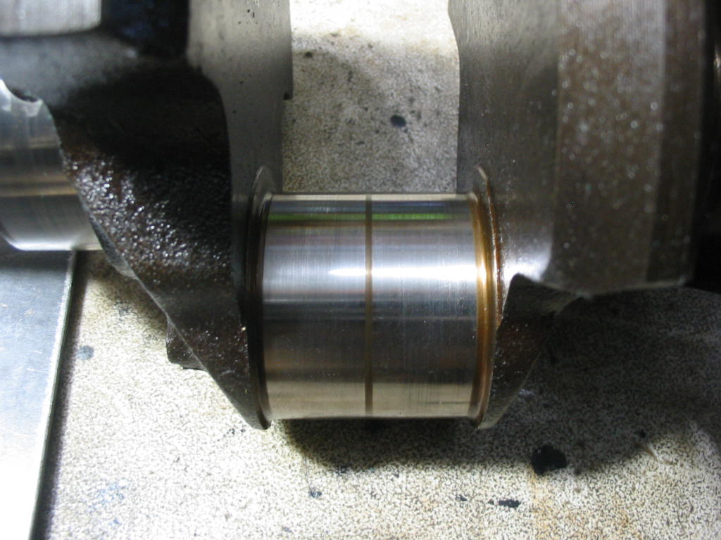
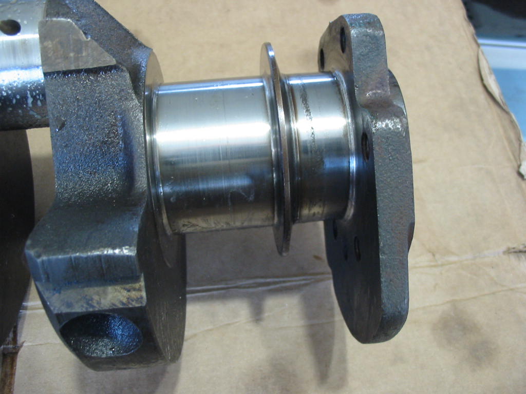
The rear seal mating surface is not nice at all. 20 years of sitting and some condensation rested on the crank in that spot and I can’t get the pitting out with hand polishing. I may have to live with a little leakage at that point. Although the engine when it was running, didn’t leak excessively from that point. More came from the trans front seal – red oil.
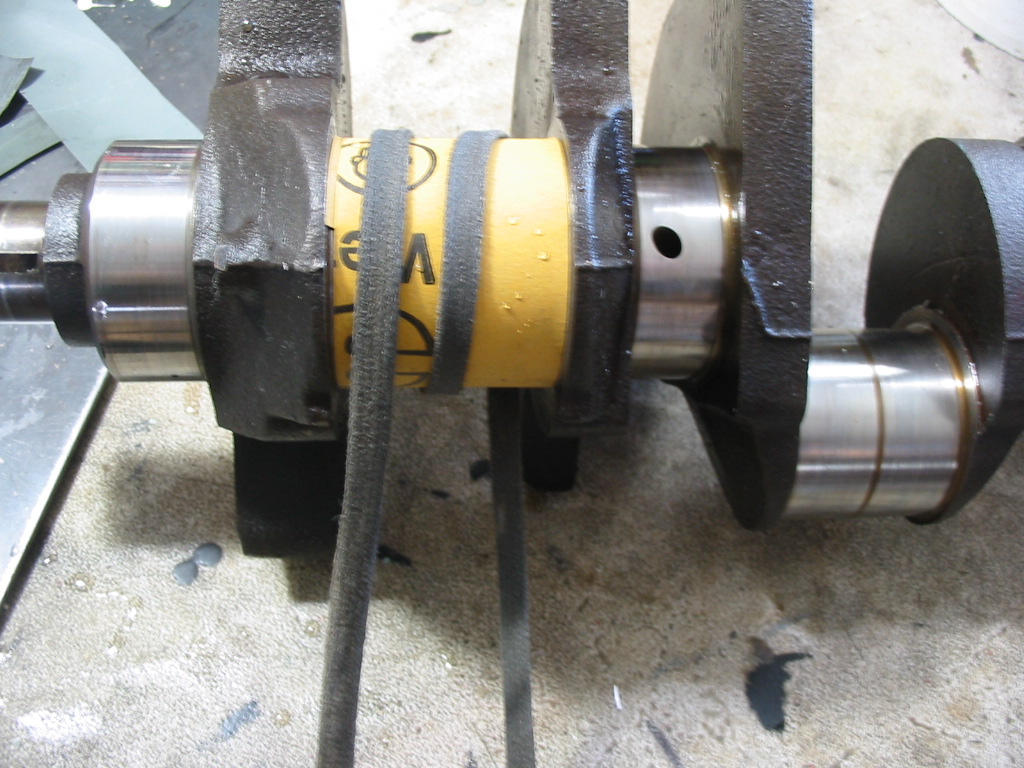
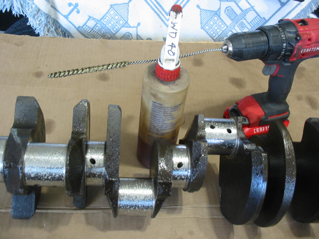
Last task in the crank cleanup is running a brass wire brush and WD40 through all the cross oiling holes. With that done the next job will be to set the crank in place with the new main bearings and check the play with plastigage.
I’ll want to hone the cylinders before I start setting the crank in place.
I tried using my bar hone to do the cylinders but for some reason the cross hatching looked course even with lots of oil. The oil may have been too heavy.
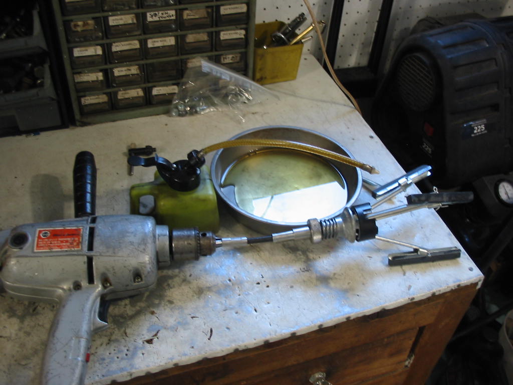
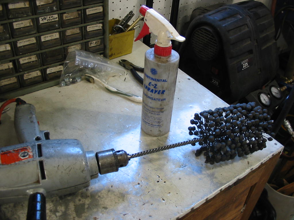
I borrowed a ball hone from my buddy Don and went at it spraying varsol on the ball and in the cylinders.
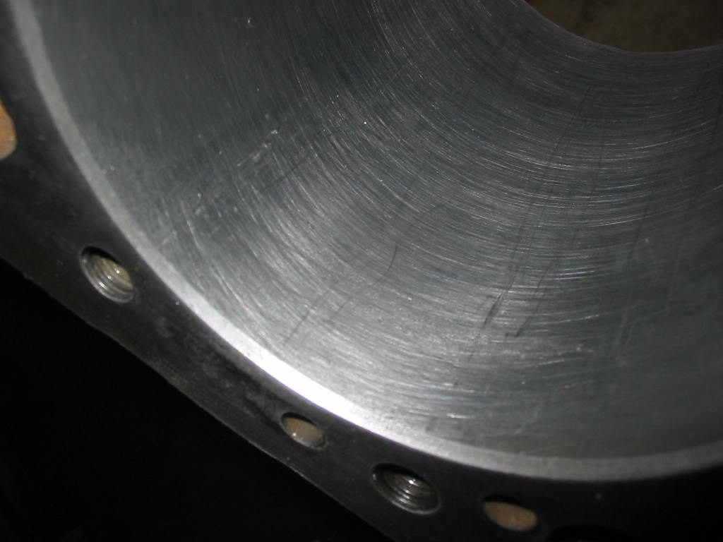
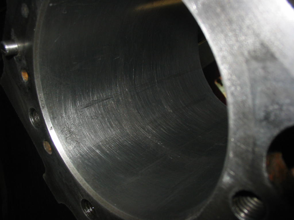
I came up with a nice fine cross hatch. There are still some minor imperfections, but the engine ran fine before – baring the burnt valve – so I don’t see why it shouldn’t with new rings..
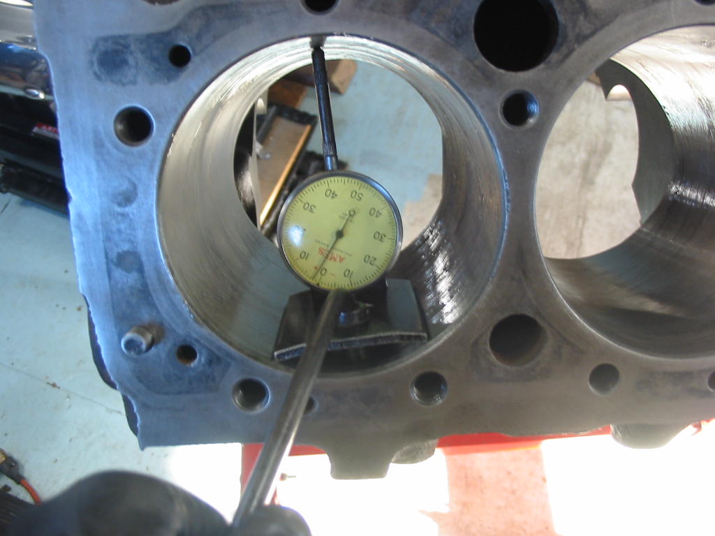
The out of round measurements are all 0.0015 or less and the taper is .002 or less. That is a bit outside of the limits in the GM manual, but what I am reading online about GM 350 engines says that I’m OK with it’s present shape – not perfect, but likely serviceable for a good may miles.