Some difficulty getting the right short shaft out, but it finally came off. This happened on one of the clips holding the universal in place. Nothing to grip on the ends of the broken clip and I don’t have a tool to grip the thin edge. I have pushed the universal away from the clip and then using a small nail punch I got the remaining part of the clip to slide around in the groove. I then was able to get a small screwdriver blade to just slip over the clip and pry it out enough to drop out of the groove. Once that happened I was able to tease the rest out.

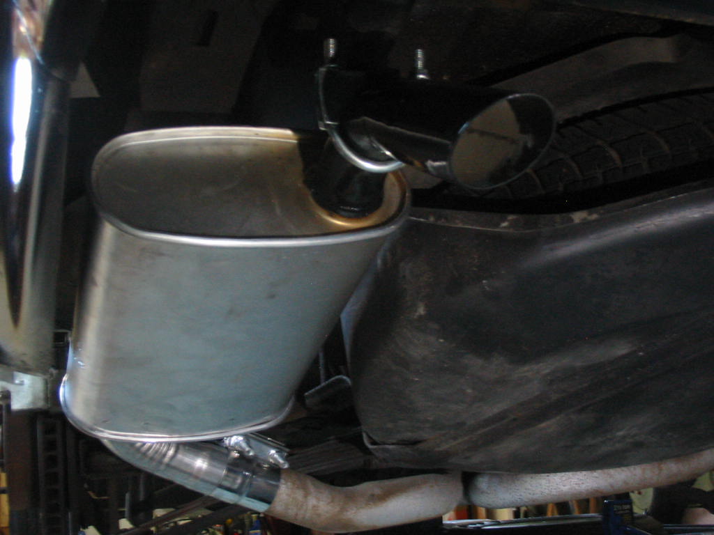
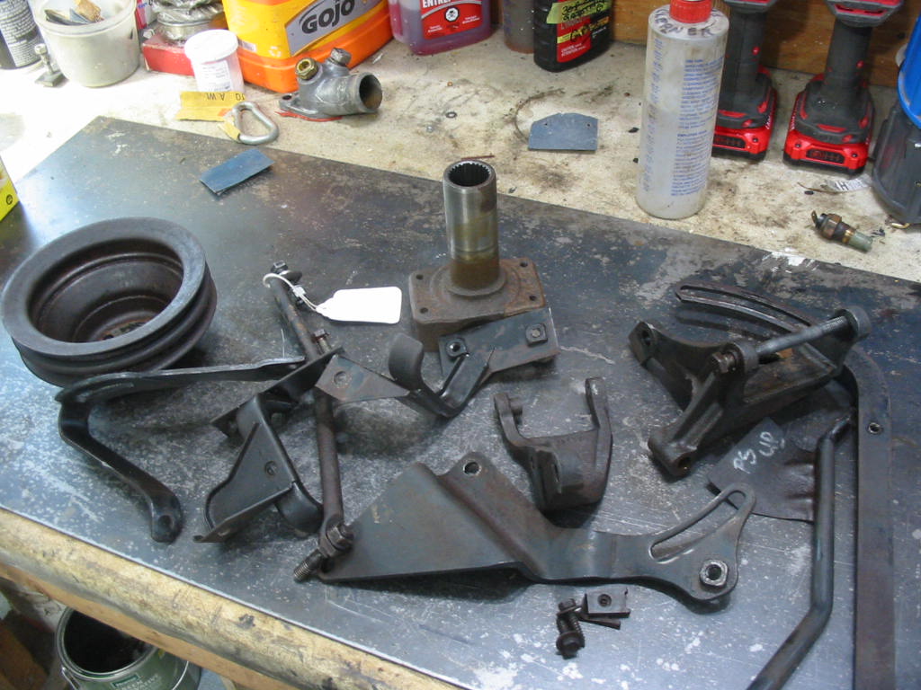
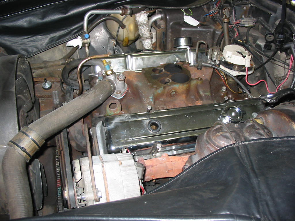
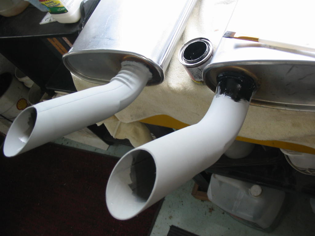
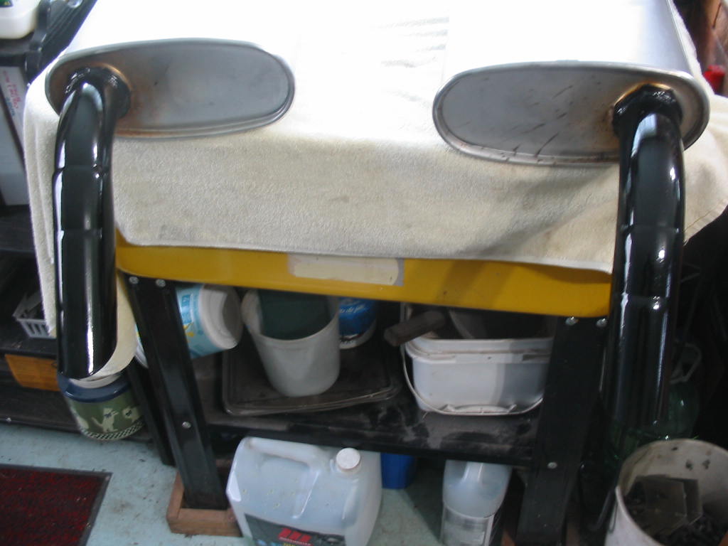
Lots of shiny parts ready for the engine install.

I had a small wire cleaning brush in my stash. I cut the end loop off and then used a drill to give the trans yoke mounting hold a good cleaning. I also used it on all of the differential yokes and got all the old corrosion out.

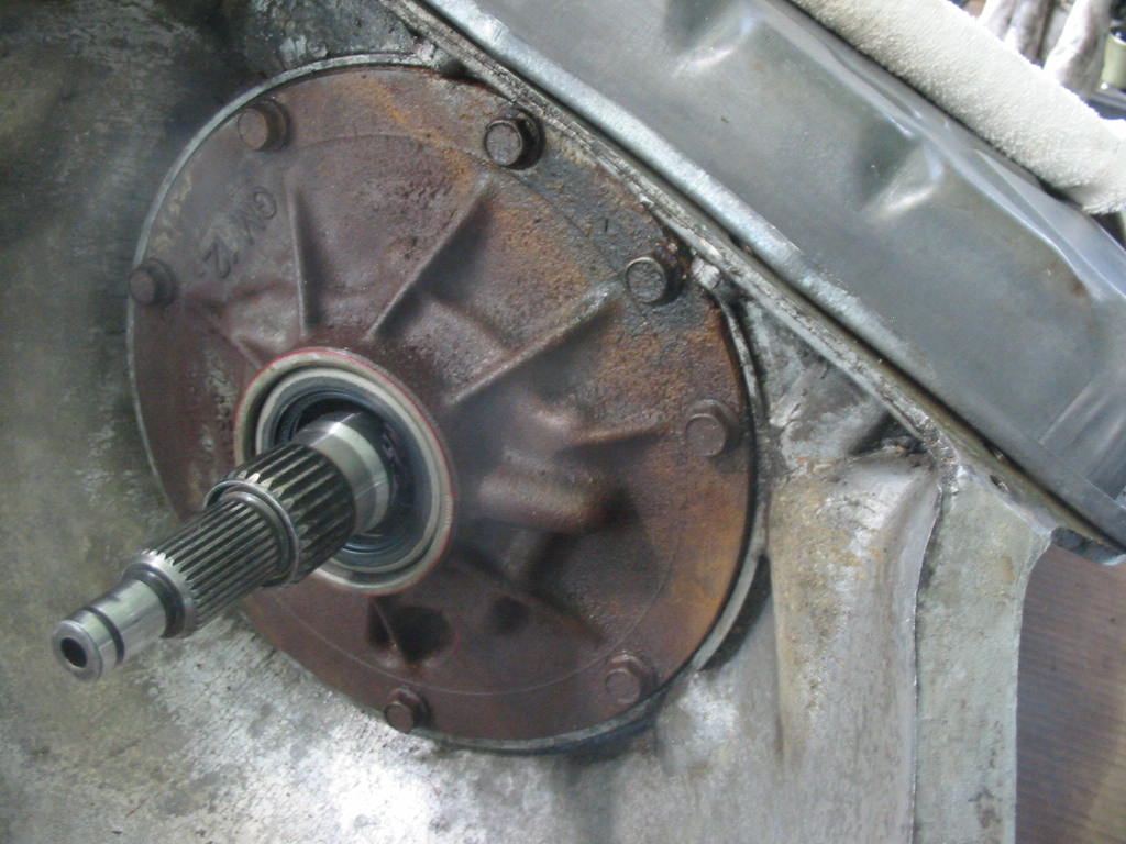
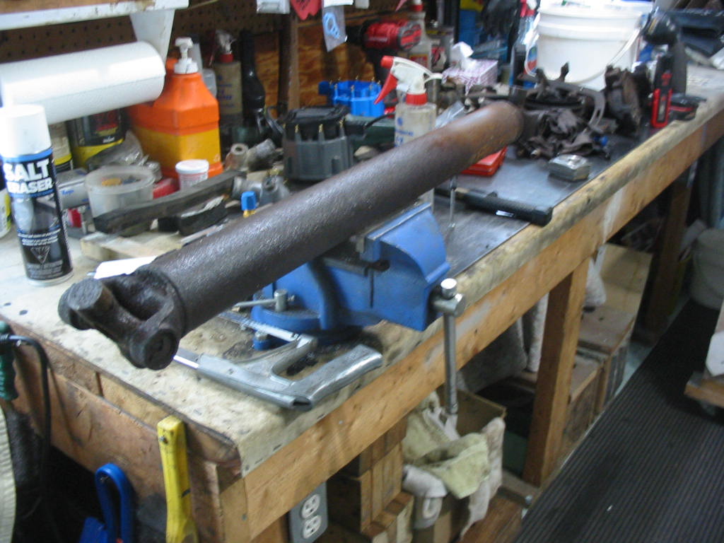
The trans yoke was a bit rough where the seal fits so I used some 1500 grit paper and a sports lace to clean it up and then I polished it with emery cloth.
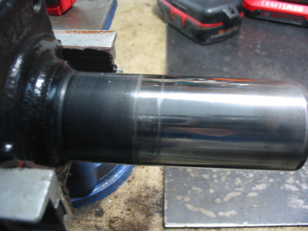
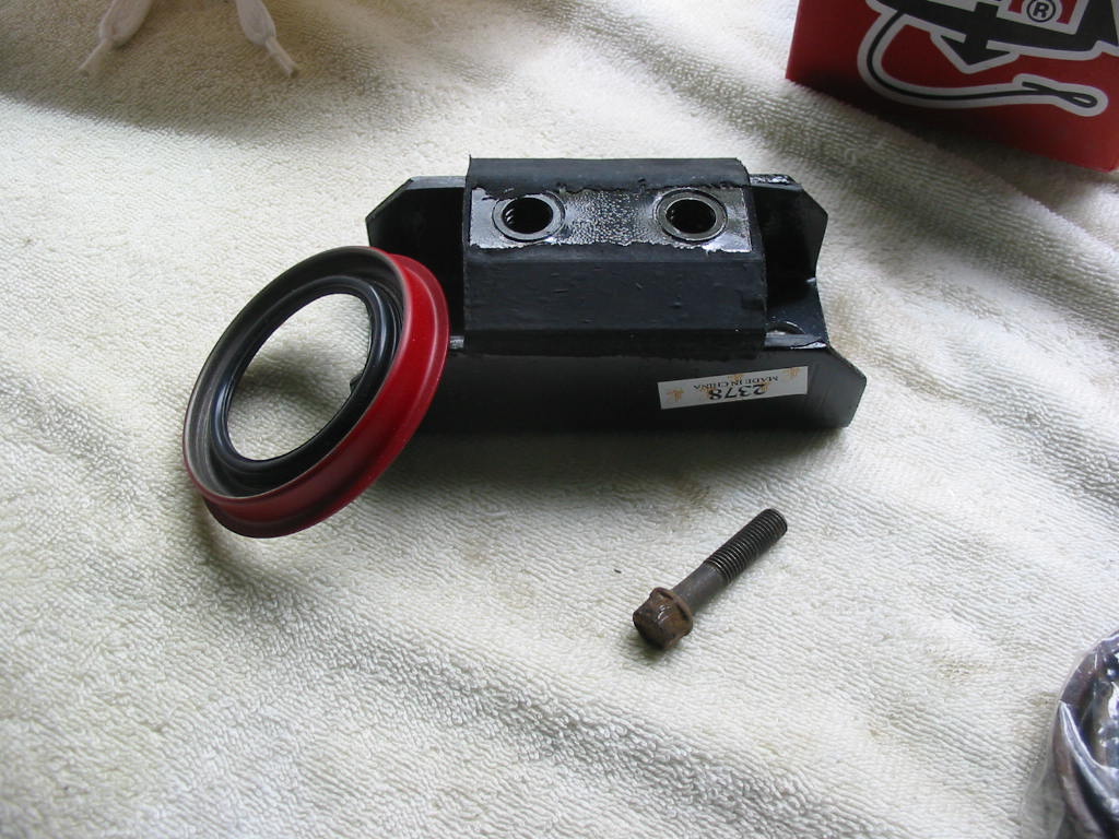
Hard to get a clear shot of a shiny part. The seal surface is much nicer, but there is a small section that is a bit rough. I leave it as is for this install and expect a bit of leakage. I may repair the yoke with a sleeve for the next install if it does actually leak.
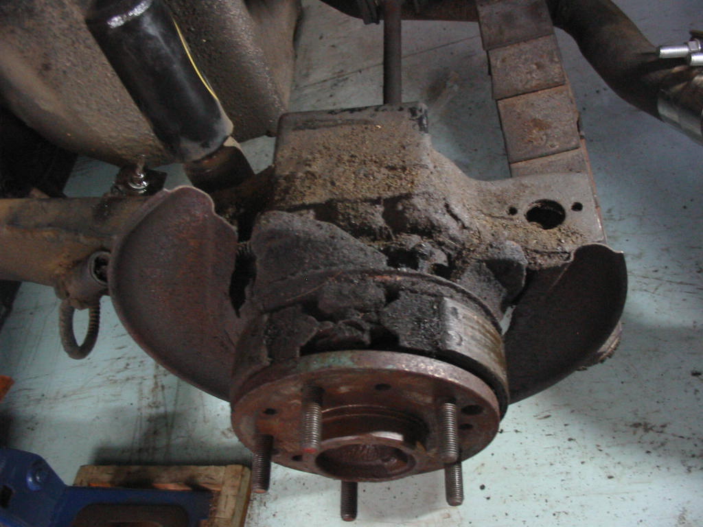
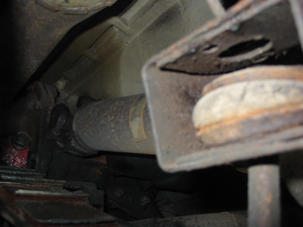
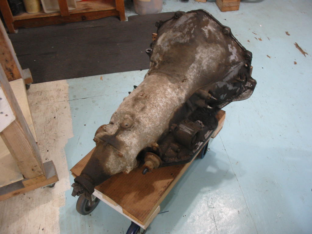
Time to get the short spindle bearings removed. Lots of crud to clean out.

Some of the brake, parking brake parts and camber adjustment bolt. Cleaned, sandblasted and painted with a coat of aluminum rust paint. Should keep them nice for quite awhile.
Next: more bearing work.