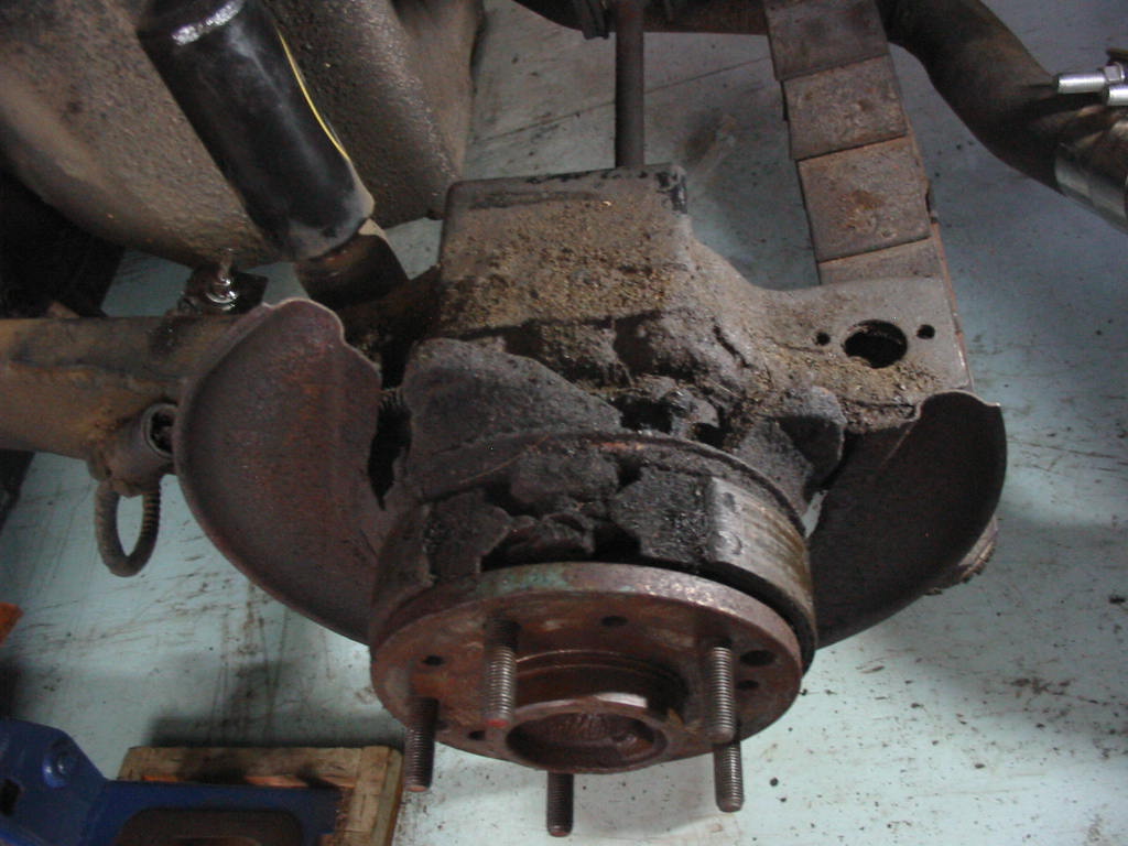
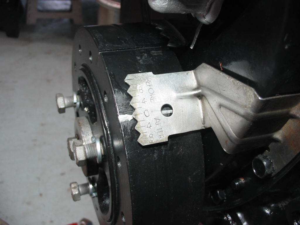
I broke the standard 3/8″ threaded rods trying to get the spindle out so I bought these extra strength rods plus grade 8 nuts.

One more go and I actually broke off the new rod. And that was with lots of heat on the spindle. There is no rust showing on the spindle or bearing so rusting in doesn’t seem to be the problem. Time to take the unit over to my buddy Don to see what can be done. It’s a difficult assembly to fit in a press, but we’ll just have to see what can be done.
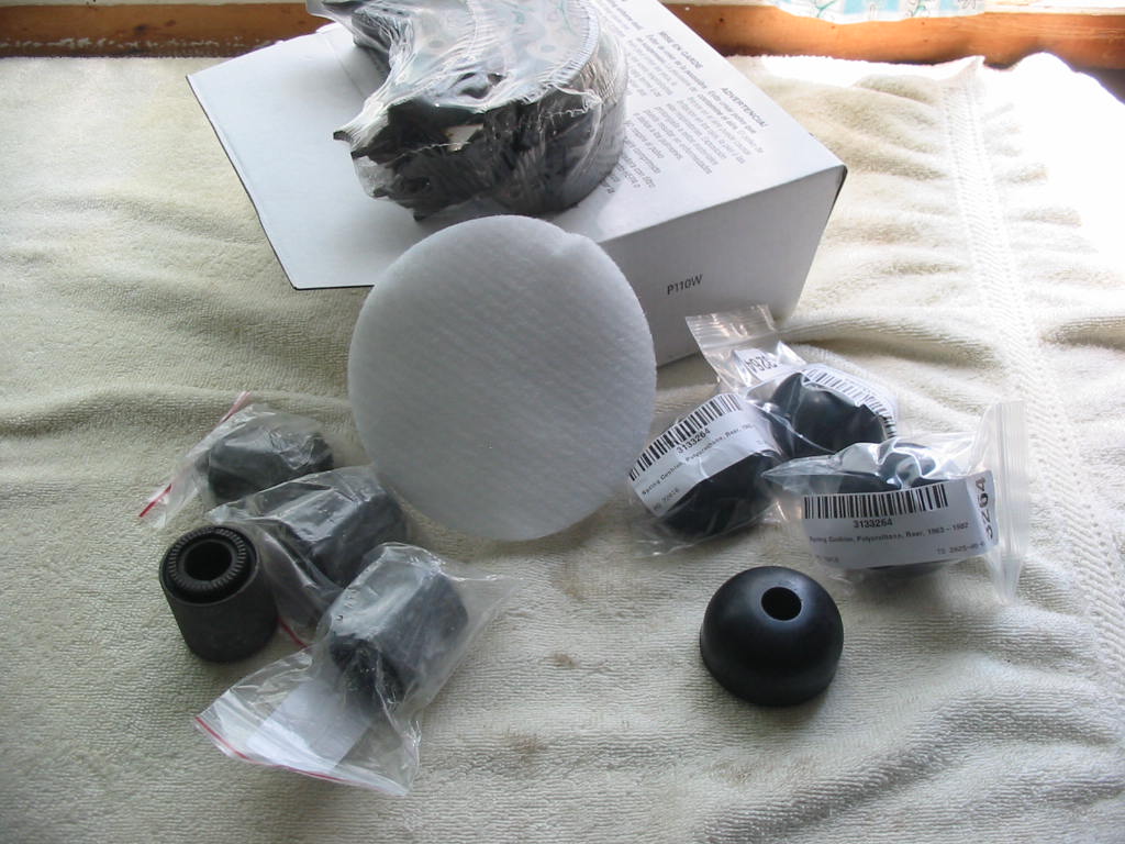
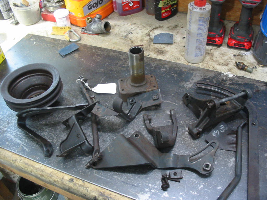
New parts came in. The parking brake pads, a fuel vapour canister filter, bushings for the rear camber arms and bushings for the rear spring mount.

Drilling out the camber arm bushings. Removing the shock mount arm mounts from the bushings was a tough push – used my buddy Don’s large press.

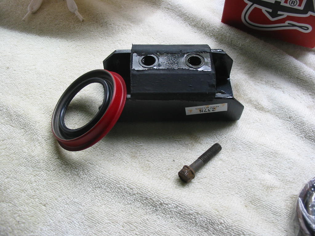
New bushings for the camber arms. I’ll paint the arms then take them to my buddy to press them in.

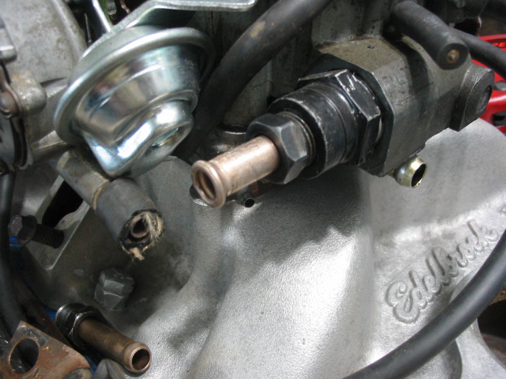
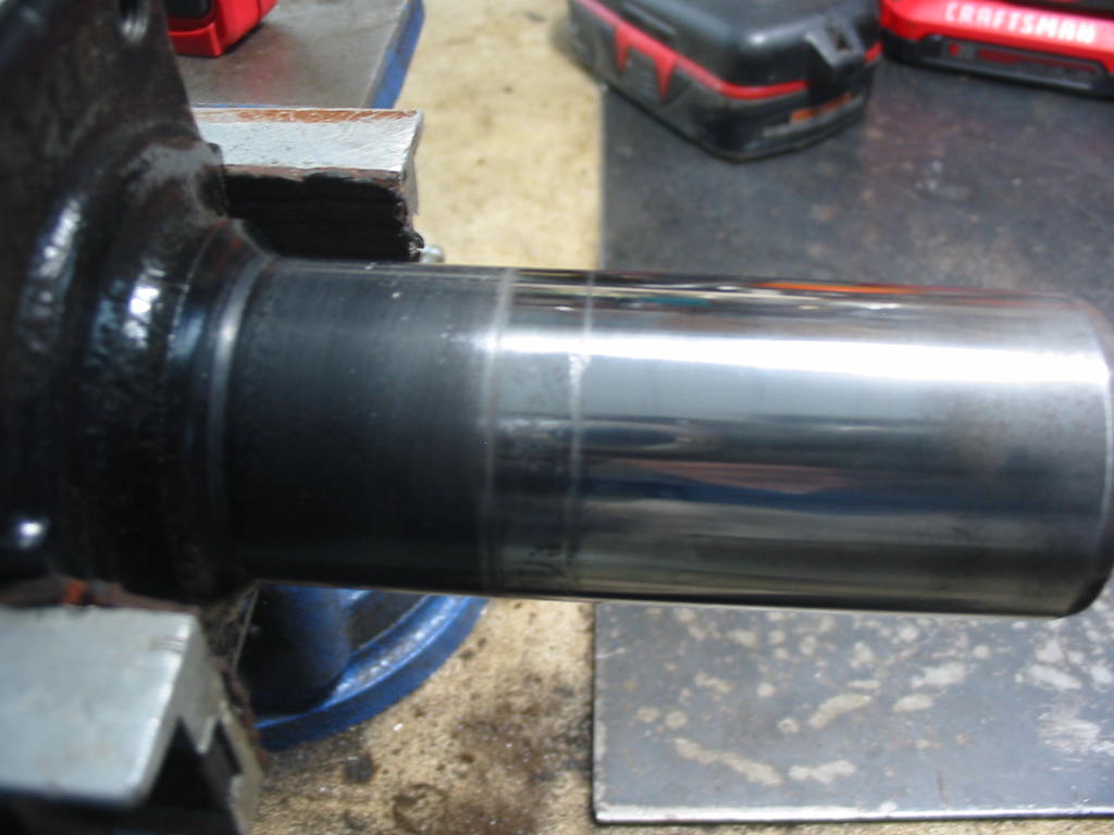
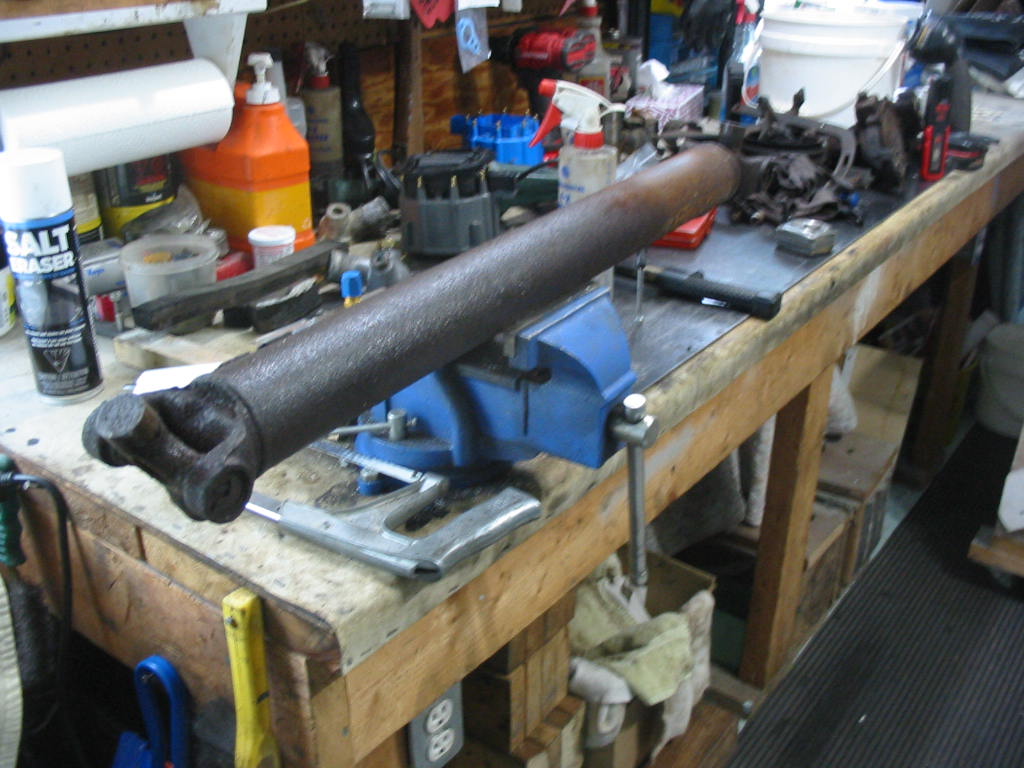
Meanwhile I have the drive shafts and yokes painted so time to put in the new universal joints. I’m using permanently lubed joints so no need for future greasing:-) The bench vice works best for me to get a nice flat and square squeeze to get the cups started into the driveshaft.

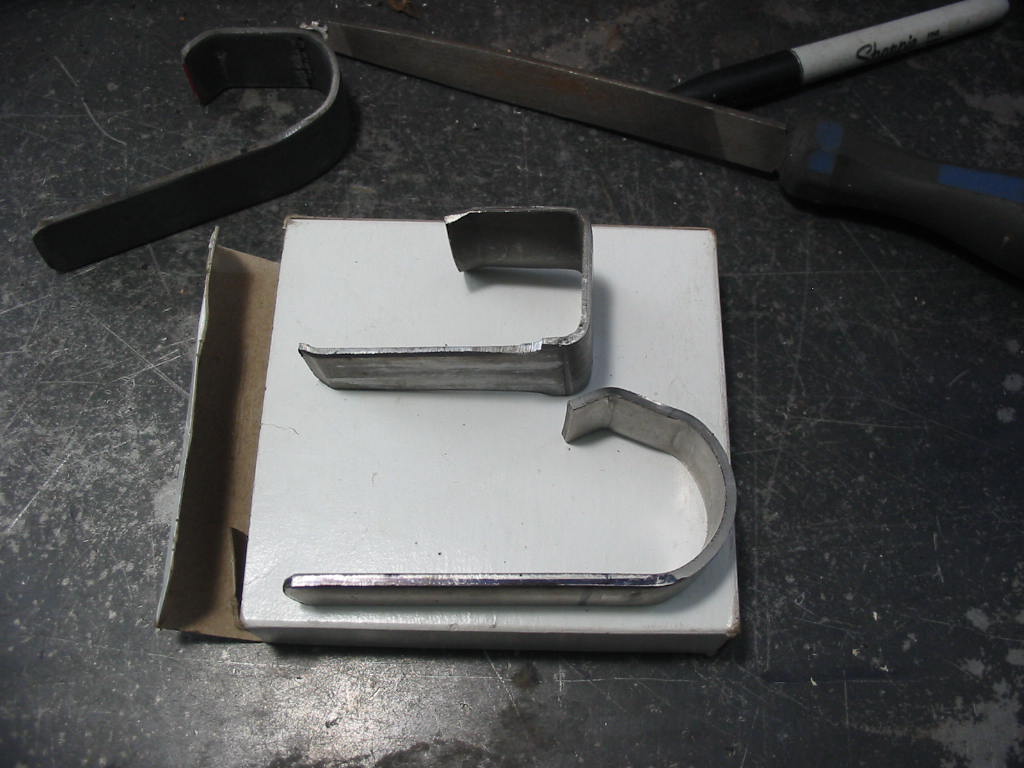
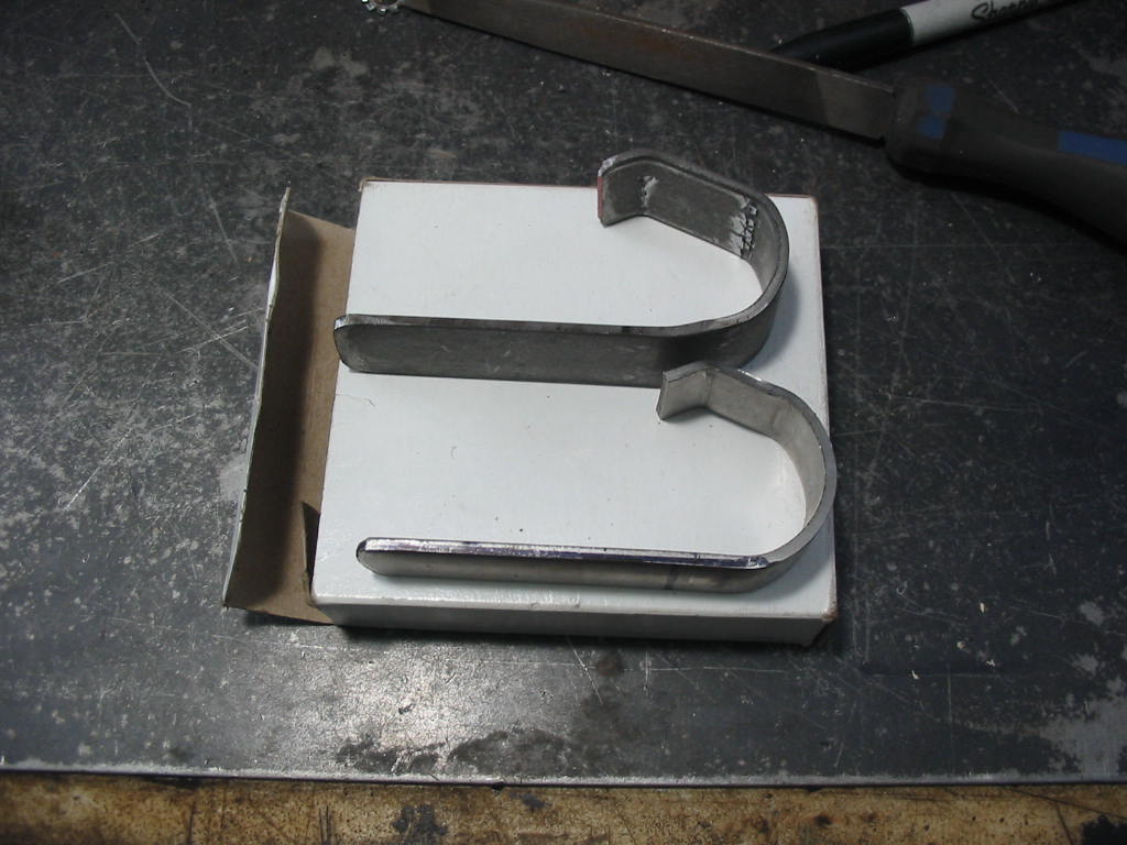
Once the cups are flush with the driveshaft yoke I used this tool to push the cups in just enough to get the clips in place.
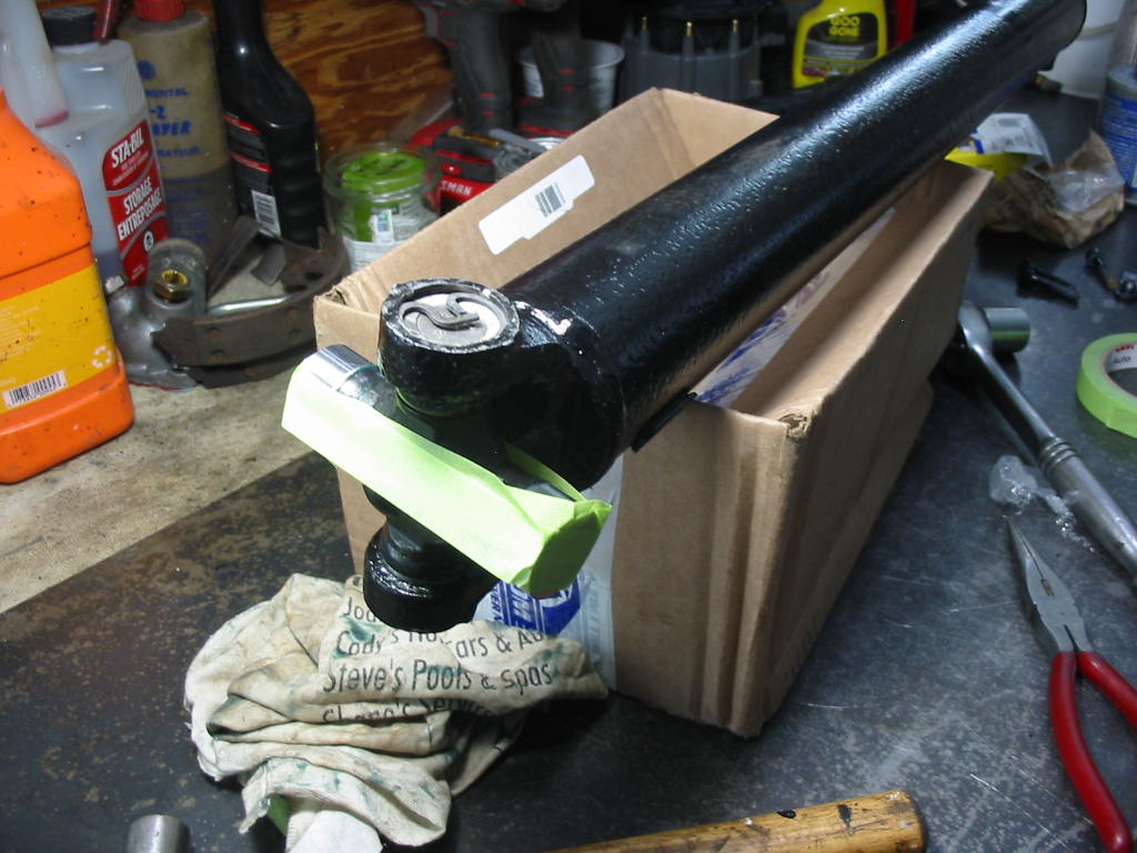
One down and five more to go. That’s a bit of masking tape over the free cups to keep them in place until I get the shaft in place.
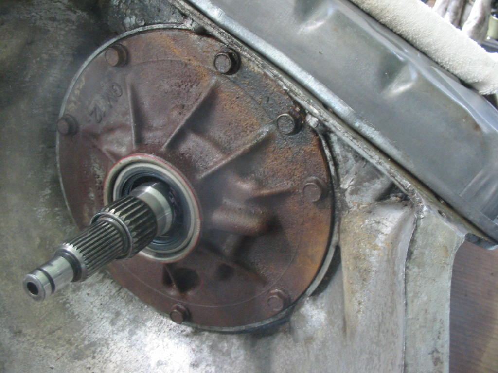
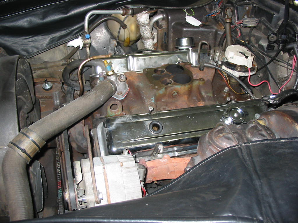
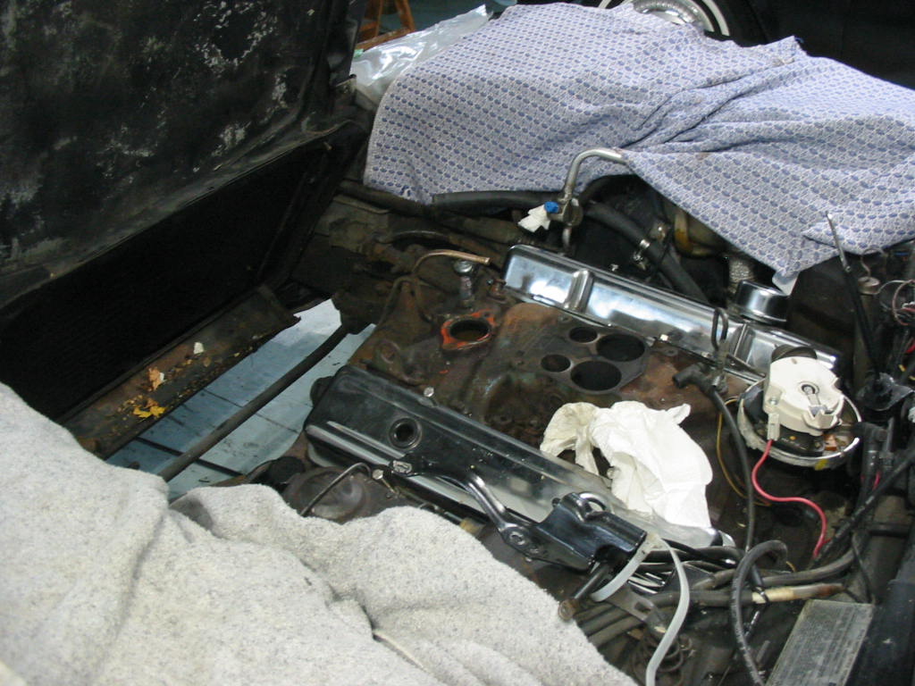
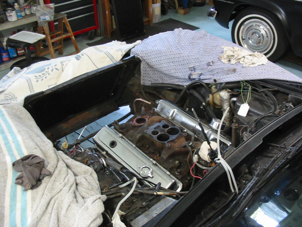
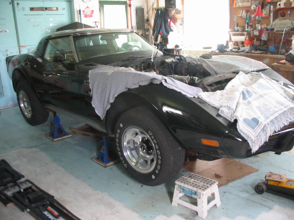
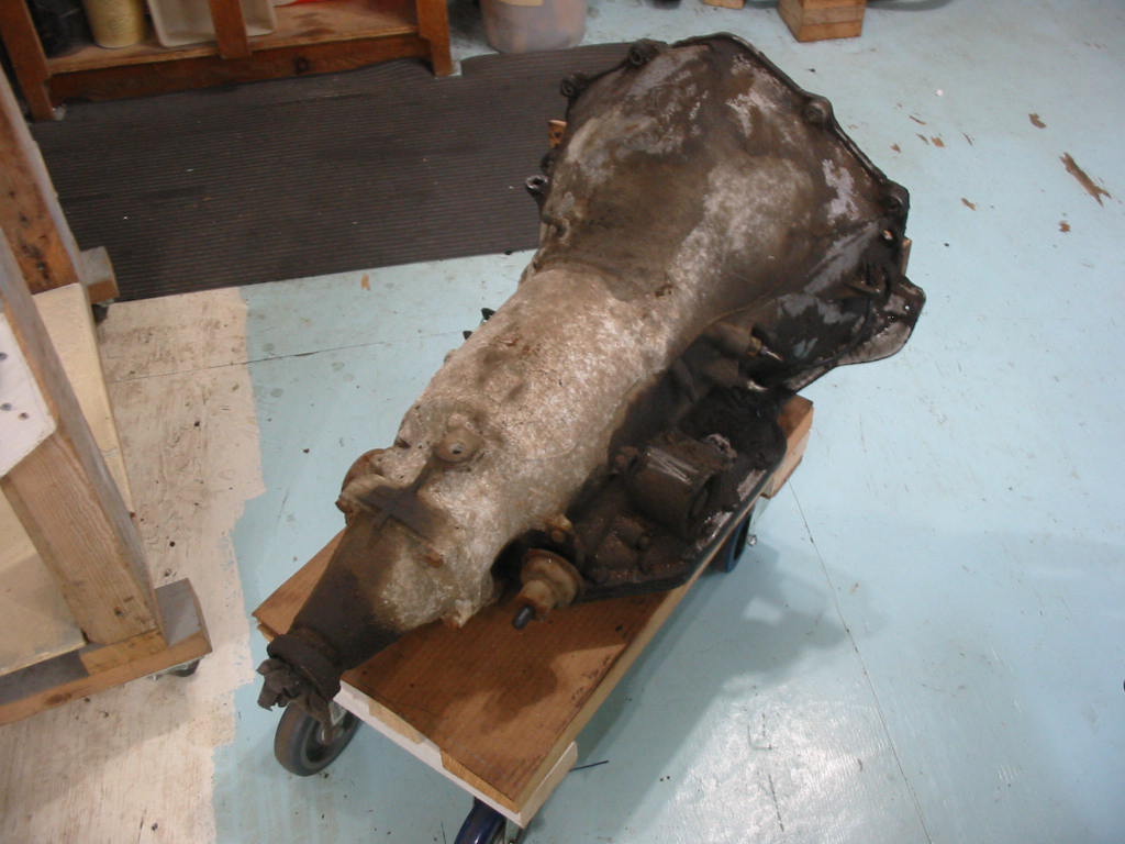
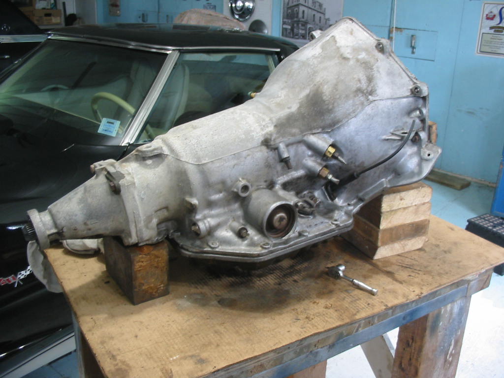
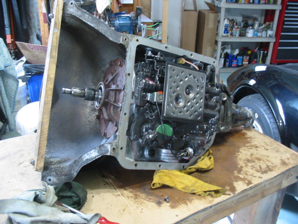
The object of this work was to swap out the engine and trans. I’ll get to that once I get the rear suspension, etc re-done. It’s taking a lot more that usual because the Corvette setup is so complicated compared to the usual rear end setup that isn’t independently sprung.