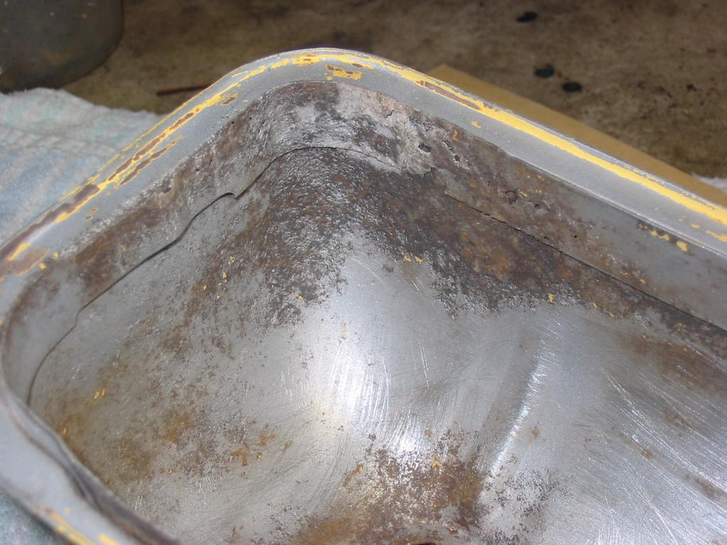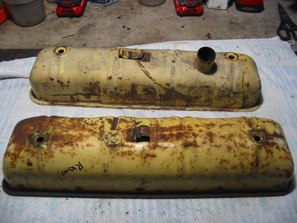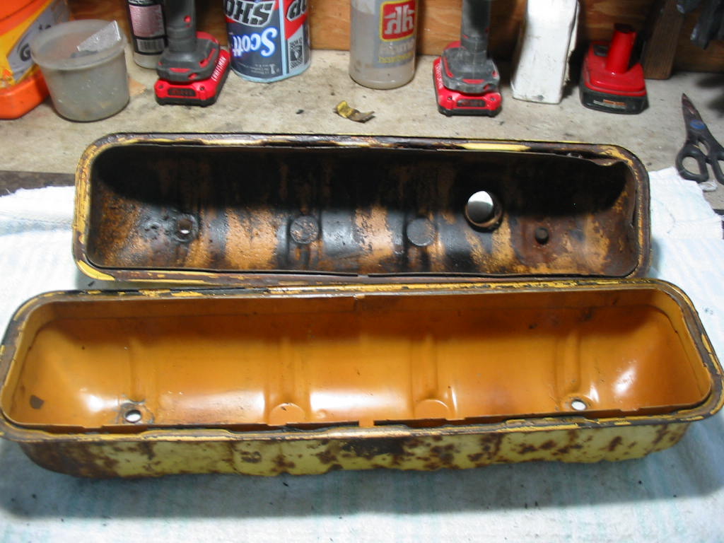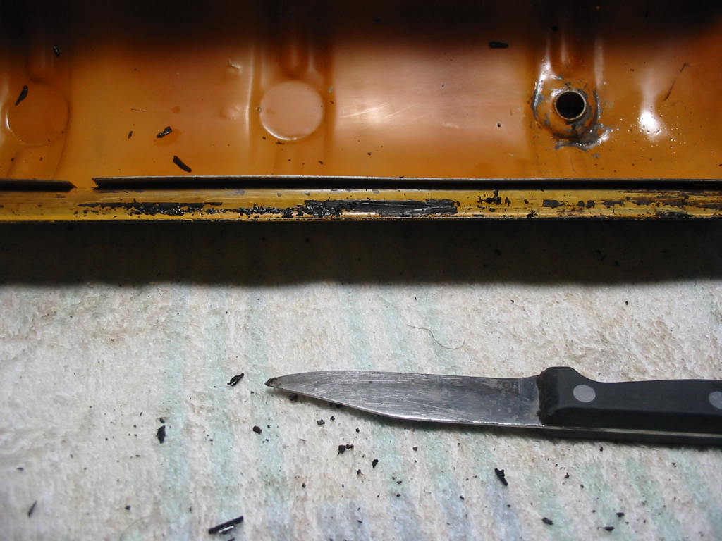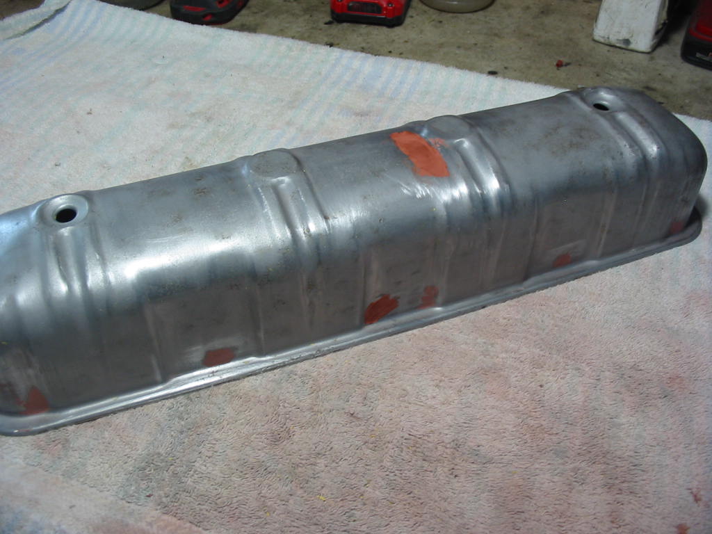
A few areas needed a second go-around with spot putty to fill in the spots were the first application of the filler shrank.
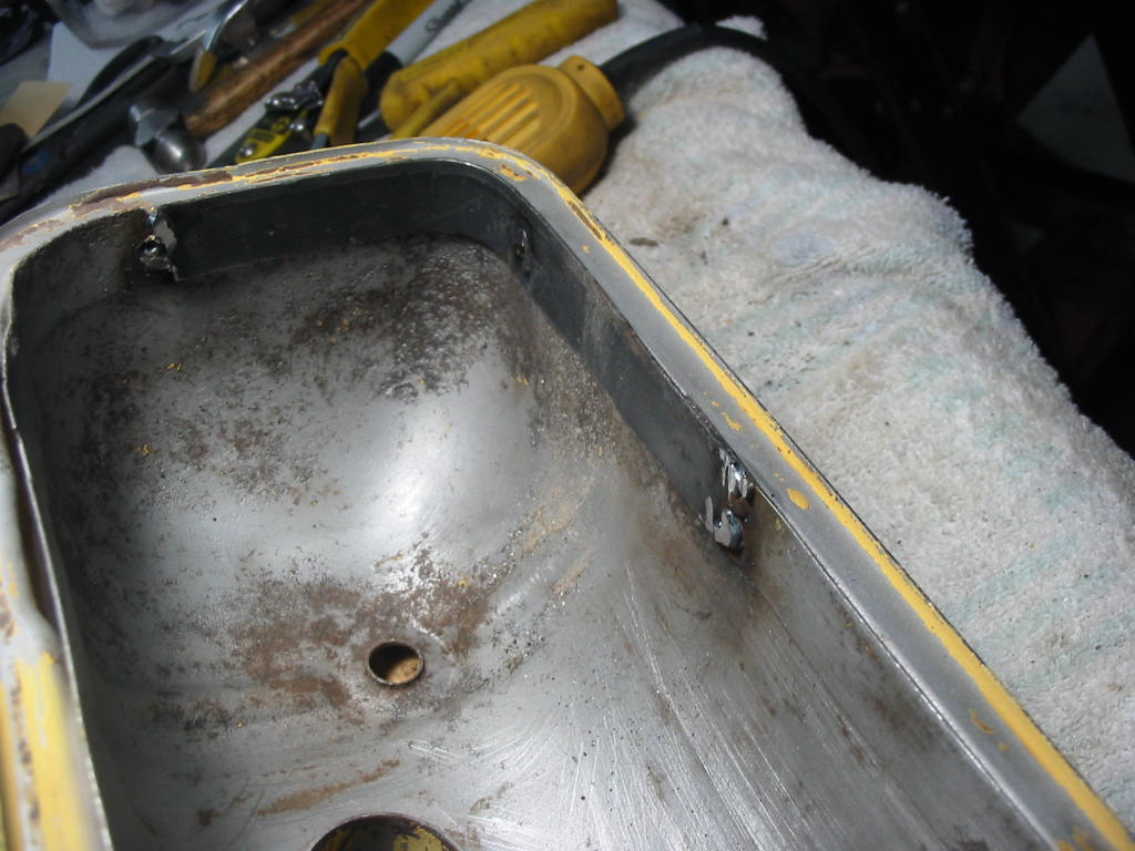
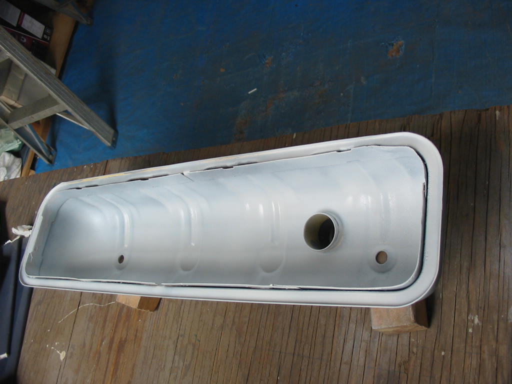
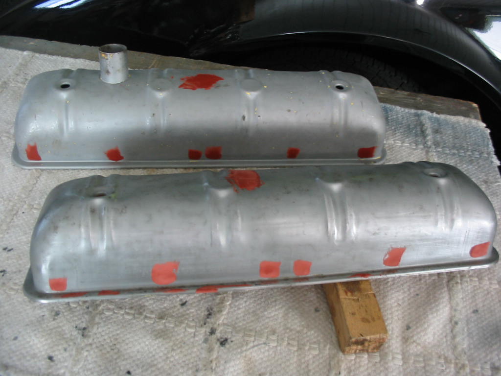
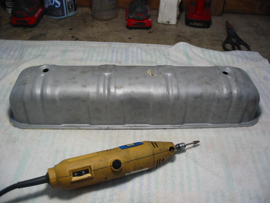
I’ve given the underside of the repaired cover a coat of white rustoleum oil based primer
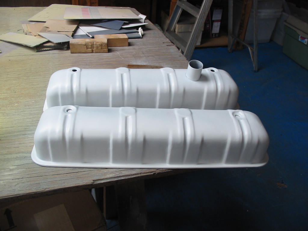
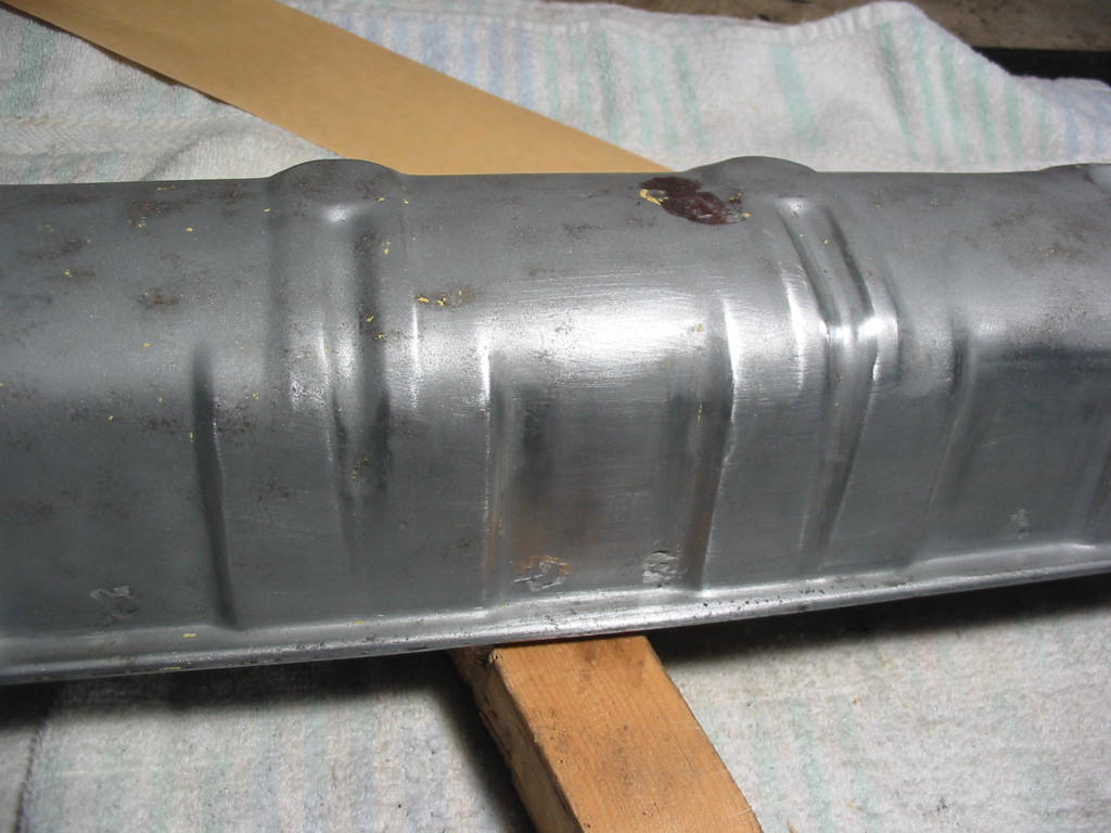
Outsides with a double coat of white rustoleum primer. Good enough to paint. I’ll leave them for a day for the primer to set properly.
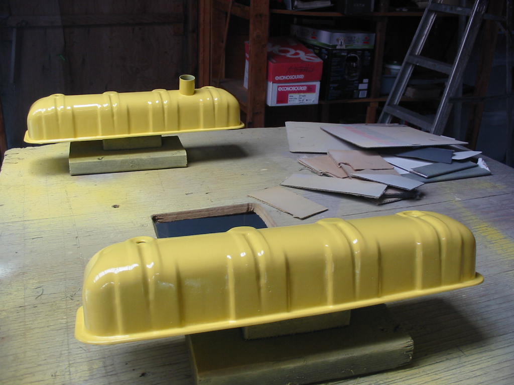
After a day I have put on two coats of sun yellow Rustoleum oil based paint. I’ll leave them for three days and then rough them up with 1000 sandpaper before adding two coats of Rustoleum clear coat.
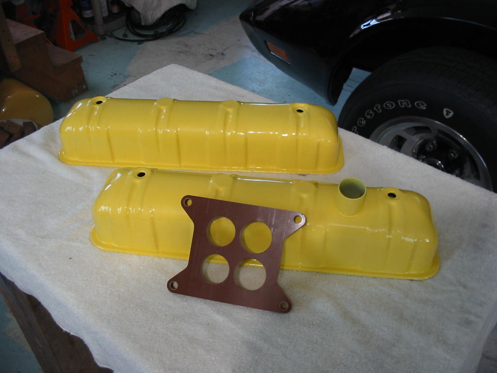
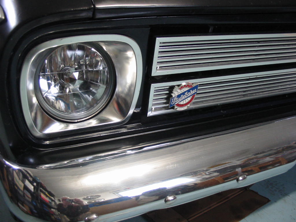
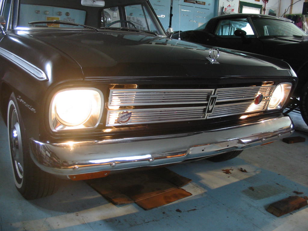
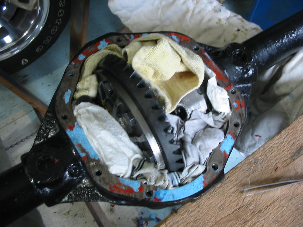
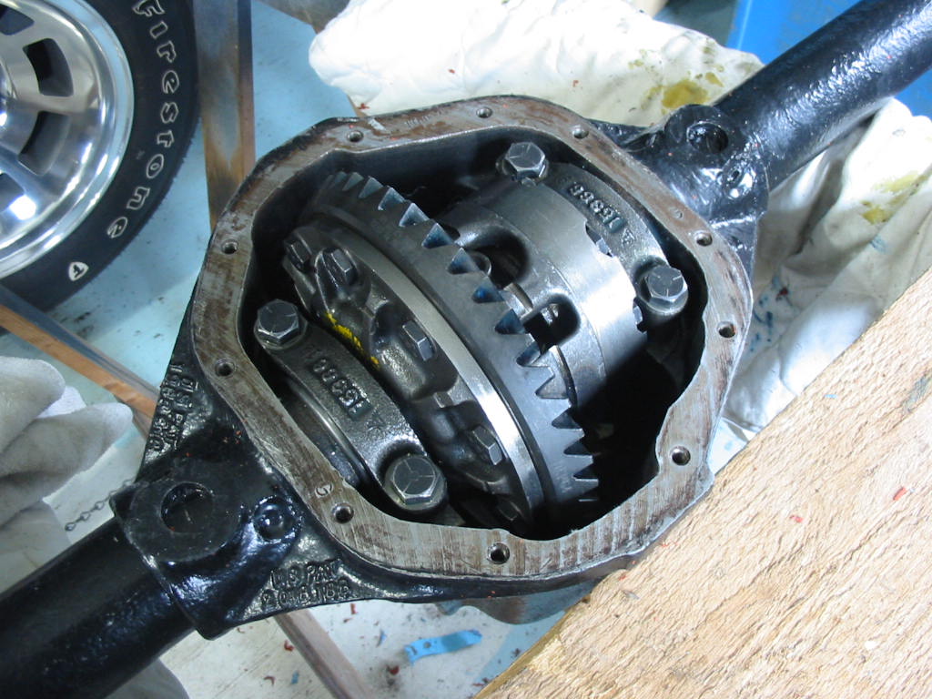
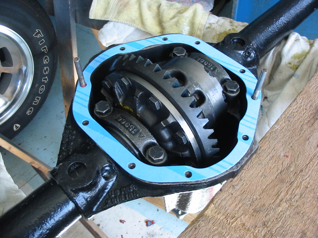
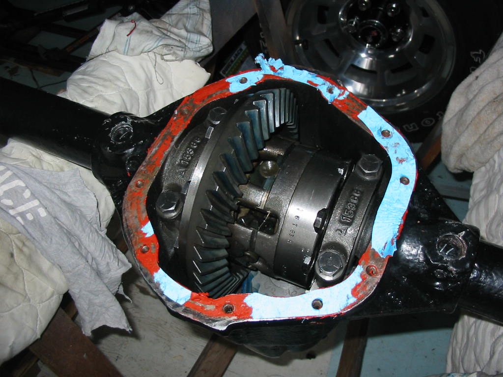
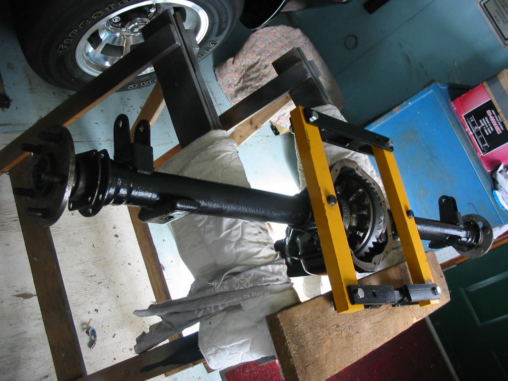
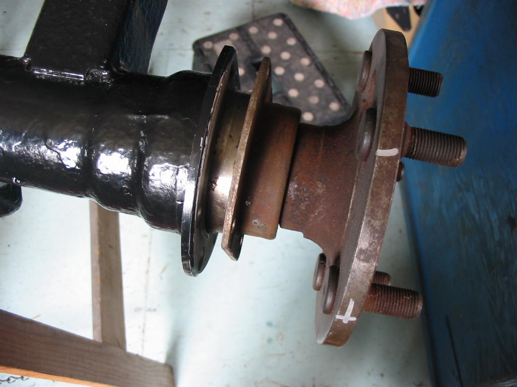
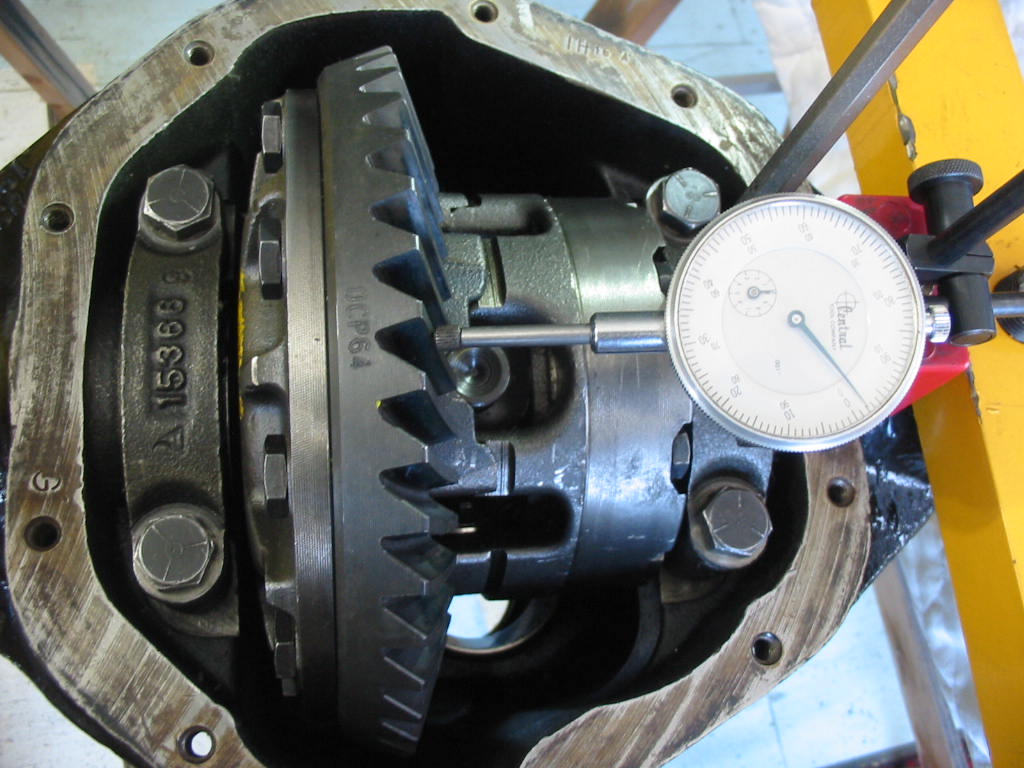
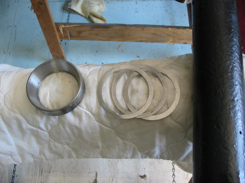
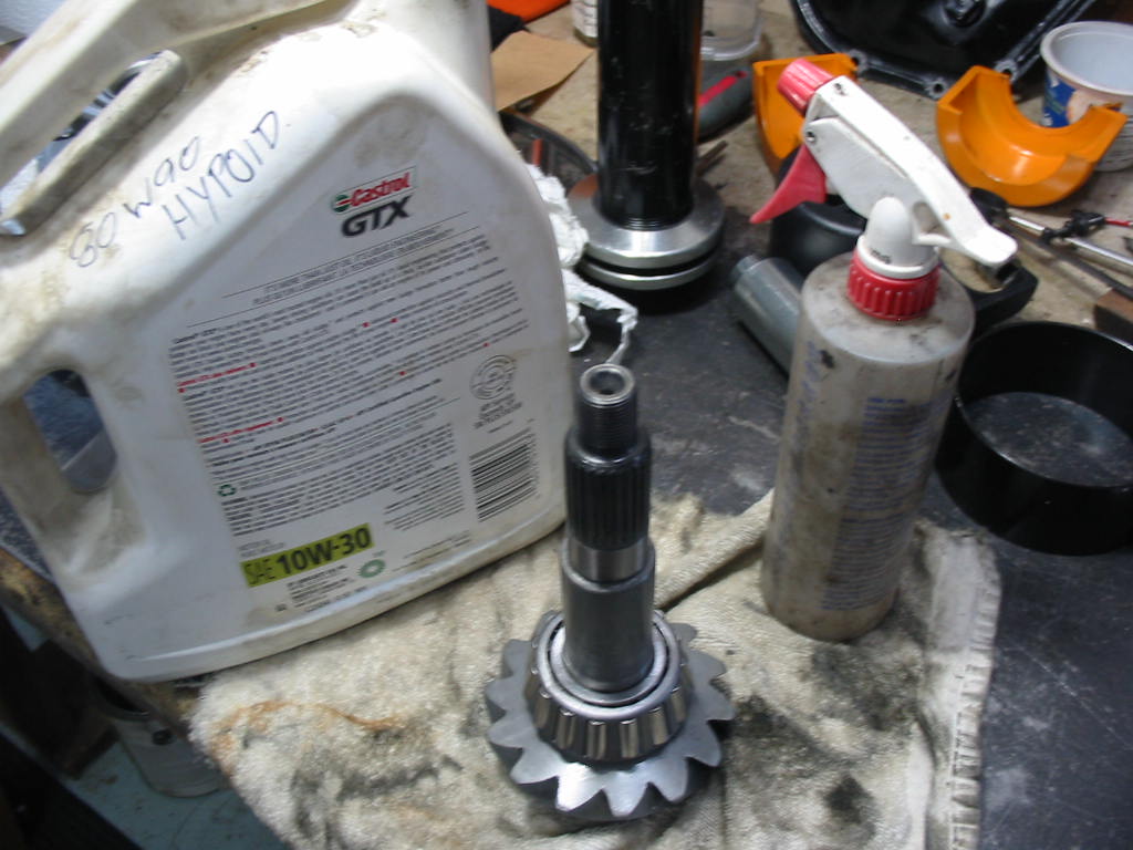
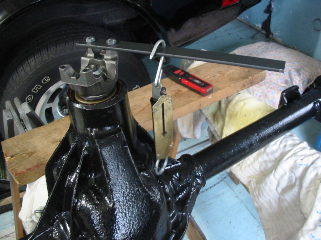
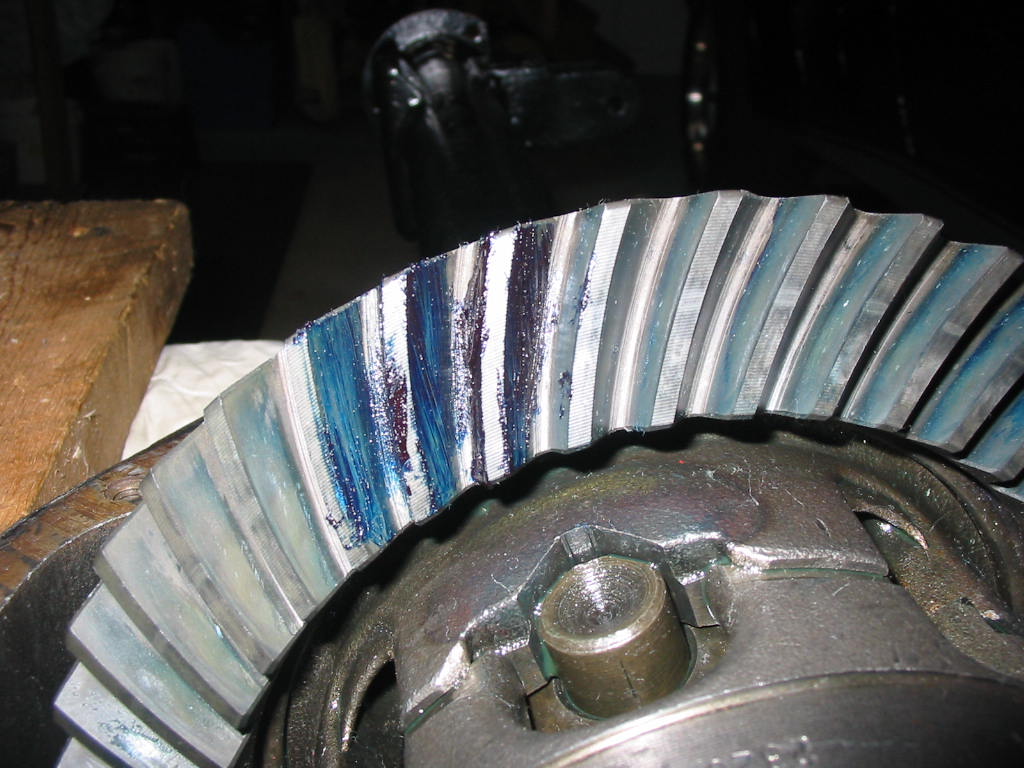
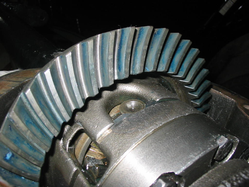
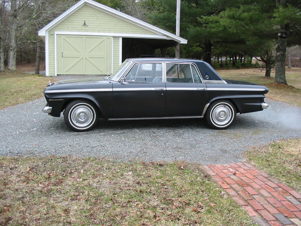
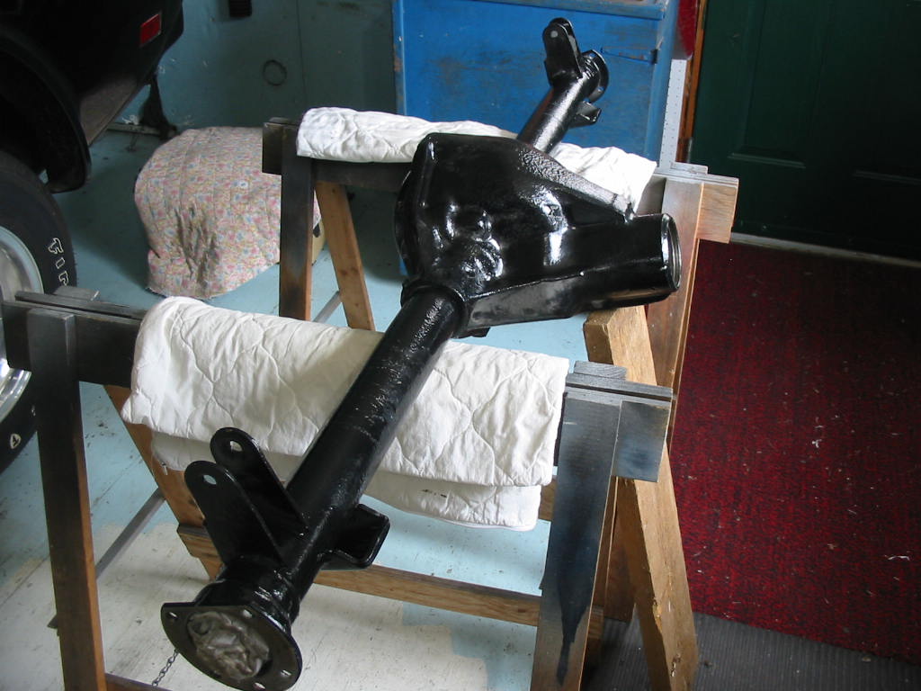
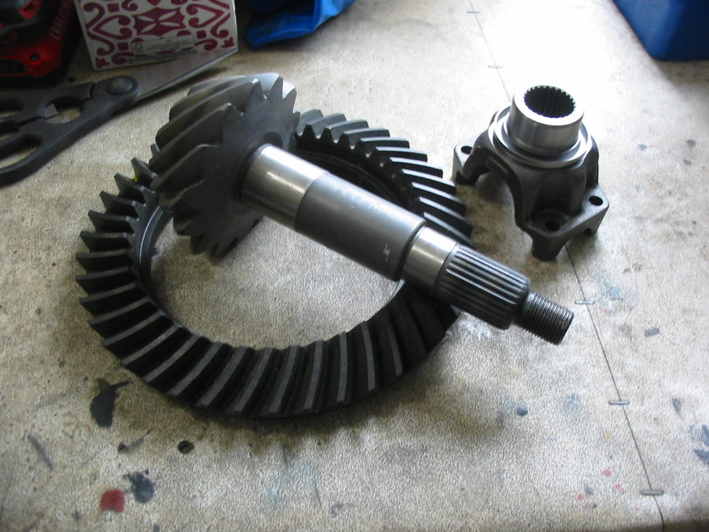
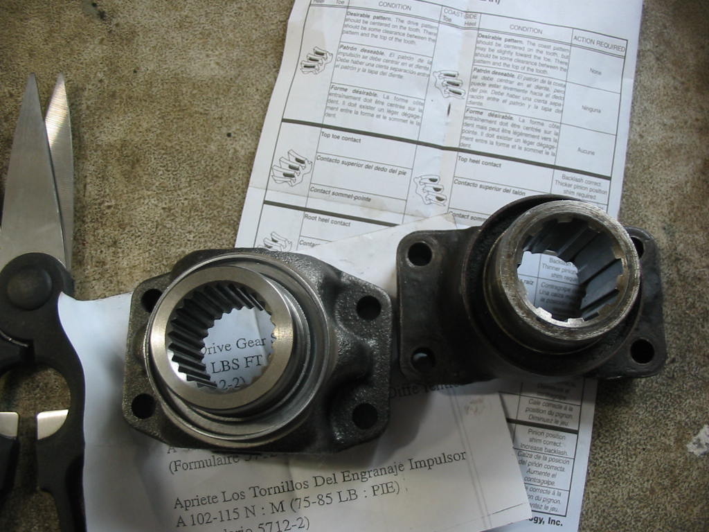
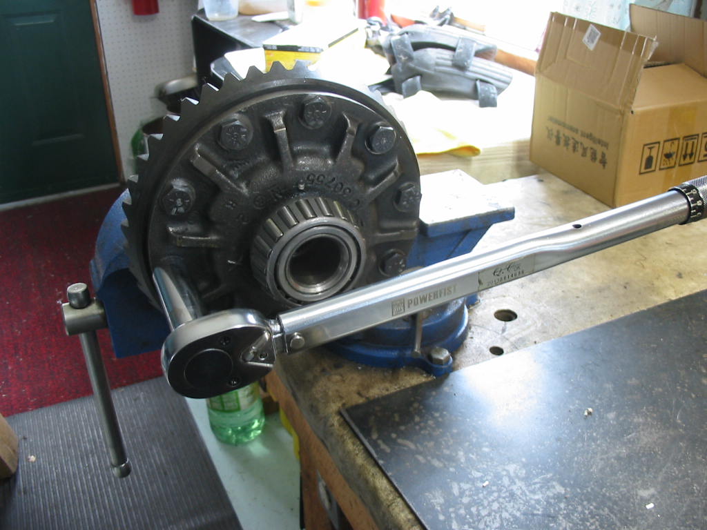
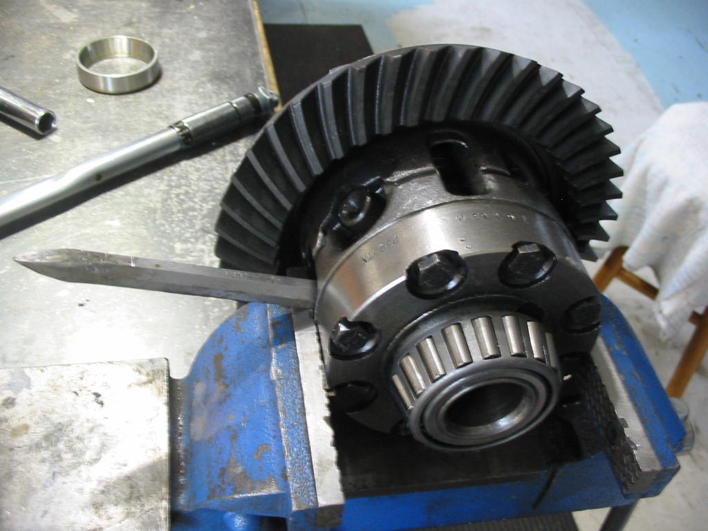
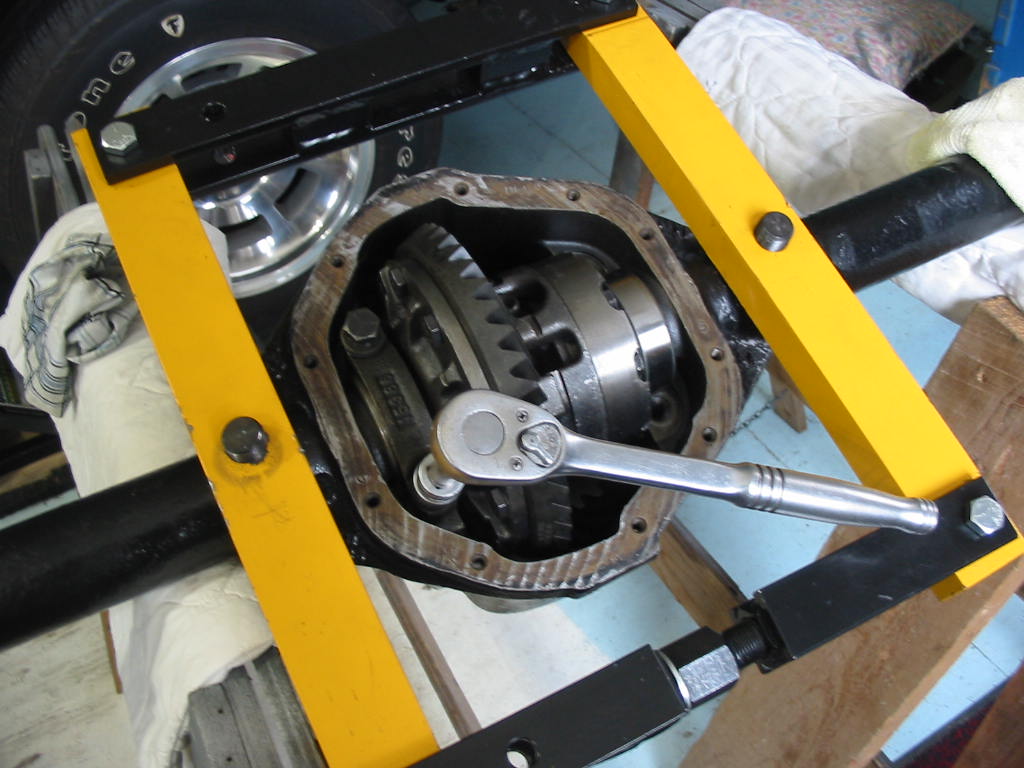
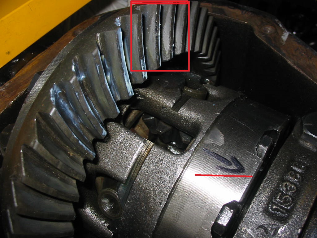
All nicely finished in bright yellow that Studebaker V8s had from the factory. In front is a 1/2″ spacer for the AFB on the 289 R1 engine in the ’66 Commander. I’ll add it to the existing 1/2″ block under the carb to get a full inch that is supposed to be optimum for the original intake manifold. On a trip to PEI the Commander got about 22 mpg with the AC on. So maybe it will give me 23 w\o the AC. It gives me 17 on every day driving. So not bad I think. I don’t expect anything especially noticeable from the extra space except maybe a bit crisper response and a wee bit better mpg. It will be interesting to see how the engine performs when I swap in the 3.07:1 Twin Traction rear end – I’ll be doing that next winter along with a complete refurbishment of the ’79 Chevy front end.
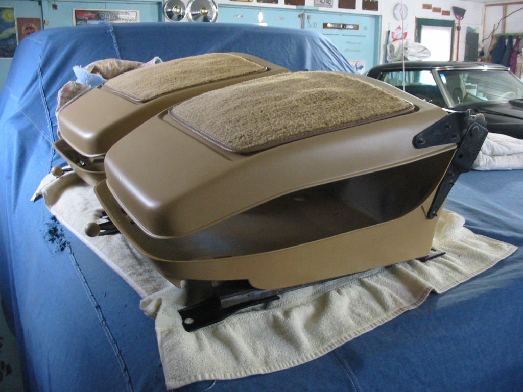
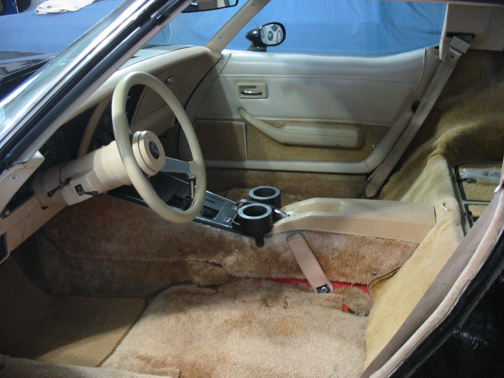
Still waiting for my Chevy’s seats.