Dana 44 differential wrap up

After more that a few tries I finally got the right combinations of shims under the rear pinion bearing race (cup) to give me a reasonable wear pattern on the crown gear.

Lacking a race extraction tool I used the brass bar on the left and a small maul to remove and install the race. Not the best, but there are crescent shaped cutouts in the differential casting for this type of removal. I used the same tools to replace the differential side bearings which I also had to do a number of times to get the spacing right for a good wear pattern and the correct backlash.

I picked up this unit to remove the side bearings on Amazon. I had to remove the bearings a number of times before I got the wear pattern and backlash right.

It is recommended that the housing be only spread apart .020. Rather than open it up to the .020 I decided to just do the minimum by only going enough to cover the .008 side bearing preload required

With .045 shims on the left and .015 on the right I was just able to slip the TT unit in the housing (without the spreader) – snug enough that it took a pry bar to get it out. I figure there was likely .002 clearance. Just enough to allow the unit to slip in place with a few taps from a rubber dead blow hammer. The manual calls for .008 preload on the side bearings. So I added .010 (.002 plus the .008) to the left side and then had to move .005 from the left side and move it to the right side to get a good backlash. I needed to spread the housing a little over the .010 for the TT unit to slip in. That would be less of a spread than the .020 recommended.

The TT unit slipped in with some help from the dead blow hammer and a final check on the backlash showed about .004 – recommended between .003 and .006.

Believe it or not the next thing I did was to dissemble the TT unit and the pinion. With all the work I did I expected that there would be some brass, metal and paint slivers throughout the assembly. Also I used a lot of chassis grease to hold things in place during the operations.

I cleaned everything up using brake clean and a tub of clean parts cleaner and then blew it all dry.

Same for the housing.

Pinion back in place with lots of hypoid gear oil over everything to stop the raw metal from flash rusting.

The TT unit being reassembled with hypoid gear oil over all and in the side bearings.

These are the two thrust blocks that fit in a hole in the centre of the cross arms. I was at a loss as to how to hold them in place until I realized that they are held together with a 1\8″ roll pin. No worry about them falling out when the axles are finally put in place.

A fine bead of sealant for both sides of the gasket.

Gasket and cover both in place aided by two guide bolts.

Bolts in finger tight. Tomorrow I’ll torque them to spec and touch up the paint ready for install over the winter sometime.

Meantime I’m hoping to see my donor engine soon 🙂

Doors and more

My cup shims have arrived. Everything I need to finish the Dana 44 rear end I now have – I hope! I need to finish up adjusting the driver’s door on the Chevy before I can get back to the rear end.

The sound deadening mat can be cut and fitted any old way – good coverage is better than look because only you will get to see it. I found the small roller very helpful especially when flattening overlapping joints.

One thing I discovered about Kilmat is that it is made in Russia. I’ll not be buying any for of it for sure – I’m not going to give Putin any more money to do the evil things he is up to!

I scraped off the factory sealing compound from the inside of the door before applying the sound deadening mat. I ended up with a ball about half the size of a golf ball. The thickness of the mat plus the factory sealant might have kept the door panel from sitting flat.

I finally got the door window to fit. It still won’t go all the way up. I’m hoping that the window rubbers will take a set and squish a bit flatter to allow the window the go all the way up – but then I may need a new motor. I adjusted the front track as far back as I could by using a dremel to oval all the two inner bolt openings. It was then a job to adjust the track stops (at the top of each track) and the tilting adjustment. I also had to flatten the front windshield side moulding that holds the front window seal and move it out as far as possible. There is something basically wrong with the door, but I can’t figure it out – very frustrating!

It’s near the end of the driving season and I’m expecting my donor motor any day now. So I’ll not start any new fix-it projects for the next little while.

This ‘n’ that

L-R transducer mount, throttle link and servo mounting bracket all cleaned up, painted and ready to be installed. Still need my transducer. Seems there is a mix up with the seller and I didn’t get the money to him.

Spent a couple of days on the doors getting the new rollers and anti-rattle bumpers in place. Then I’ve being adjusting everything trying to get the windows to fit properly in the door frame.

My biggest problem with the window was to get it back enough to fit in the frame opening. The front/rear movement of the window is controlled by the front vertical track I moved the top as far back as I could even to using a dremel grinder to oval the bolt openings and the frame itself.

I also ovaled out the lower track mounting bolt. In the end I got just enough rear movement to allow the window to just fit. Even so the window front edge doesn’t fit the frame rubber properly. I’ll put that down to the difference between the original frame rubber and the aftermarket ones I used.

I picked up these hole plugs for the doors thinking it was a good idea, but they really didn’t want to go in and I didn’t try to force them.

In the end the plugs really weren’t needed as I decided to cover the door in sound proofing Kilmat. Hopefully this will improve the sound of the door closing and also cut back on the road noise getting into the cabin.

More cruise parts coming in

Finally got the cruise control lever. It is a new unit. I bought it on Ebay. All went south when the seller sent it to some place in the US by mistake. I contacted UPS and logged a problem with delivery. Things started to happen, but I couldn’t follow them very well. It seems to have been sent back to Ebay and one day it appeared on my mailbox by the regular postal service which was nice as I didn’t have to pay any extra fees for delivery or even tax! I am still waiting on the transducer which is coming from Sydney NS – about 5 hours away and it’s been two weeks or more and Canada Post has yet to deliver!

Meanwhile it’s back to working on the drivers door to see if I can get it to roll up to the top with the door closed and also to get it to fit behind the clips on the upper front door seal. I’ve installed new window rollers on the regulator. I missed taking a photo to show the difference between the old and new rollers. The new rollers are different. The shank is about 1/8″ longer. It doesn’t seem to make any difference in the window operation except that the back of the front roller catches on the electric motor mounting bolt when the lower door cover is not in place. Once in place it draws the motor away from the roller mount. I also filed some off the motor mounting bolt to give more clearance. The other problem is that the mounting end of the roller splits when it is peened to the regulator arm. Maybe that is expected. I don’t know, but they seem to be holding on OK.

There is no way I can seem to get the window to fit properly so that it can be moved to to the top with the door closed. There is something basically wrong. I have yet to figure it out. I’m taking a bit of time to work on it. I’ll take the door panel off the passenger door and do some comparing. I can already see that the passenger door window sits at least a 1/4″ further back as compared to the driver’s door window. The front window track seems to regulate just how far the window sits to the rear.

Cruise parts arriving

Still waiting for shims to finish the Dana 44 rear end. Got some from Studebaker Intl and I have some on order from Stephen Allen’s.

In the meantime I came across a used cruise control transducer for CDN $50. So I thought why not collect the parts to give the EL forty-eight cruise. The transducer hasn’t arrived yet, but some parts have. I found a ‘good’ used servo plus brackets and actuating rod. I Won’t be using the blue mount as the one now in place will do fine.

I gave the servo rubber a good coat of silicone inside and out in the hopes it will help it to last longer. The other parts have been bead blasted and I”ll paint up.

Picked up two new speedo cables and a new vacuum break switch for the brake pedal. I also sourced a transducer bracket from Ebay. I’ll get it blasted and painted.

That’s all for now. More as parts arrive. Meanwhile I am driving EL forty-eight to keep things loose, but it’s not really fun with the constant engine miss caused by, I believe, a burnt valve. My donor engine should be arriving anytime.

Differential interlude

Studebaker International (one of three large Studebaker parts vendors) can supply the shims for the carrier as well as those for the pinion cup adjustment. Will likely take a week or so to get as I ship by the postal service rather than pay for couriers who add brokerage fees to bring stuff across the border.

I picked up this tool some time ago on Amazon. It’s a spreader for Dana 44 type rear ends. I will need it to put the final shims in for the carrier as the width with the shims will be .008 over the space in the differential casting. This is to preload the bearings on either side of the carrier. I read that the housing can be spread apart a max of .020. I will need most of that to slip the carrier in place.

Differential install

Something missed from the last post. The spider gears and pinions were a bit grungy and has to be cleaned up before re-assembly. I opted to use rags to wipe away all the dirt. Surprised that so much had accumulated.

To start I installed the new bearings on the carrier without any shims. I don’t have a big enough press so I put the bearings on using an old bearing cup and hammer. Works well with a little grease on the inside of the bearing and on the housing.

Used 3.54 ring gear installed with bolts tightened to 50 ft-lbs. I was a bit concerned that my carrier wasn’t right for the 3.54 gears. Checking on line I found that the carrier break point is 3.73 and lower before a different carrier is needed for 3.92 and higher. The way to tell is to measure between the bottom of the bearing and the flat surface that holds the ring gear. In this case it is a tad over 2″ which is right for 3.73 gears and lower. The measure for the higher gears is about 2.4″

Checking the movement of the carrier sideways.

At this point I have decided to disregard most of the procedures in the service manual. I don’t have all the special tools to follow the instructions which would in most cases would result in a near perfect pattern between the ring gear and the pinion. Instead I am going to adjust the carrier and pinion until I get good pattern between the gears. I will adjust the pinion location by moving the rear pinion bearing race and the carrier side to side with various sized shims keeping in mind I need to have the backlash between .003 and .006.

Checking the backlash.

This is a tool I made up to hold the yoke when I need to preload on the pinion. There is also a preload on the carrier bearings of .008

At this point I have adjusted the pinion closer to the ring gear by about .030 and I have put .020 of shims to the ring gear side of the carrier. This is giving me a nice pattern. Unfortunately I don’t have the shims needed for the right side of the carrier or under the rear pinion bearing cup. I am now stuck until I can get a selection of shims to finish the job.

Next: final shimming to get a nice wear pattern and acceptable backlash.

Differential rebuild

Clam shell kit I picked up on Amazon for about $200 taxes and shipping in. The black clam shell fits the differential side bearings and the yellow clam shell fits the pinion rear bearing. There are no instructions with the kit so if you are a novice like me you need to watch a couple of Utubes on differential side bearing removal to see how it works. One hint is that you have to have the bearing cups in place before trying to remove the bearings other wise the clam shell just pulls of the bearing cage.

In this shot the housing screws have been removed and I have marked the pinion shafts to be sure and get them back were they were originally. I’ve marked the top of the case, but I should have marked the bottom also.

Half the case removed revealing the plate and discs.

The plates are showing significant wear in some spots so I’ll replace them with a new set. The set on one side includes three plates and two discs. The inner plate is concave. I’ll replace the old set with a new set in exactly the same order and per the shop manual.

Carrier all back together with bolts tightened to 50 ft-lbs.

I inserted a flanged axle axle into both ends to align the spider side gear and the clutch friction plates to simplify the axle insertion later on.

Next: time to get the carrier and the pinion in the 44 pot.

Differential details

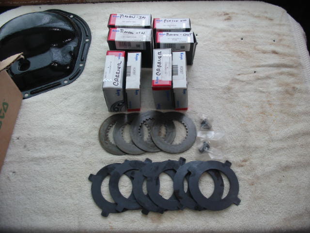
What I’m looking to replace

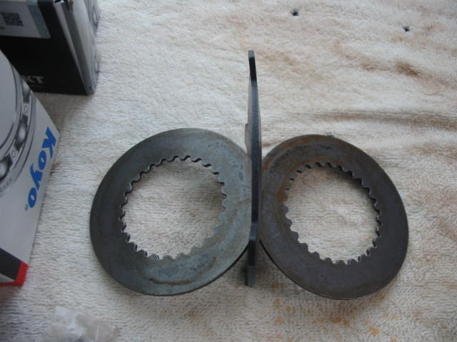
These are the two types of plates used in the TT differentials locking plates and discs. If the plates now in the unit show a lot of wear I’ll do the swap. The angle of the pinion shaft and the matching slot in the TT housing seems to be about 45 degrees which means there should be three or four sets of plates and disks. If that is the case I will need to by one or two extra sets. The parts book only shows sets plus the concave inner plates.

The toothed disks are flat as are two of the plates. The third plate of each set are concave which keeps the disks and plates snug in the TT housing.

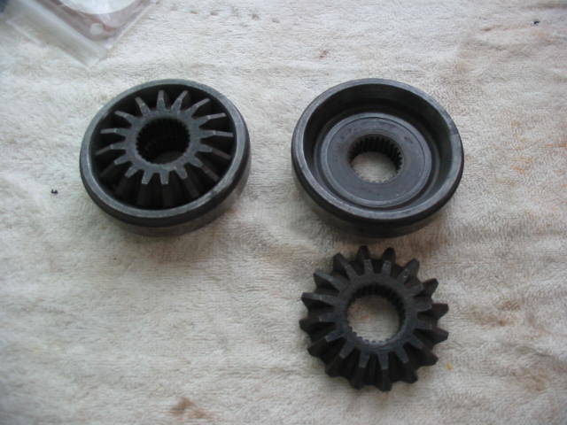
This is a new set of side gears They are for flanged axles and will replace the existing units in the TT assembly that are for tapered axles.

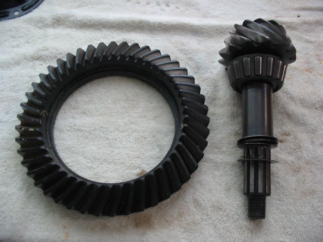
This is a 3.51:1 gear and pinion (used) that I intend to use. It ls slightly lower than the 3.73:1 that is presently in the car. It will give a slightly lower rpm for any given gear and that will reduce noise and improve mileage. The 289 R1 now in the Commander (say something around 220 HP) should handle the change with little difficulty.

Dana 44 differential build

While I wait for my donor engine I’m going to attempt to build a Dana 44 positraction rear end for my ’66 Studebaker. The centre pot and innards of this Dana44 are very similar to the Dana 44 rear ends in many C3 and C4 Corvettes.

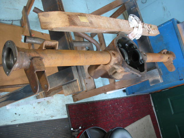
This rear end unit also has the mounts (pointing towards the bottom of the the photo) for traction bars – offered by the factory usually in conjunction with positraction and rear sway bars. Now begins the boring chore of de-greasing, cleaning and painting the donor unit. My idea is to have a complete unit ready to be quickly swapped into the Studebaker whenever I get the chance. Meanwhile it’s the summer driving season and I prefer to keep the cars on the road rather than doing upgrades and repairs.

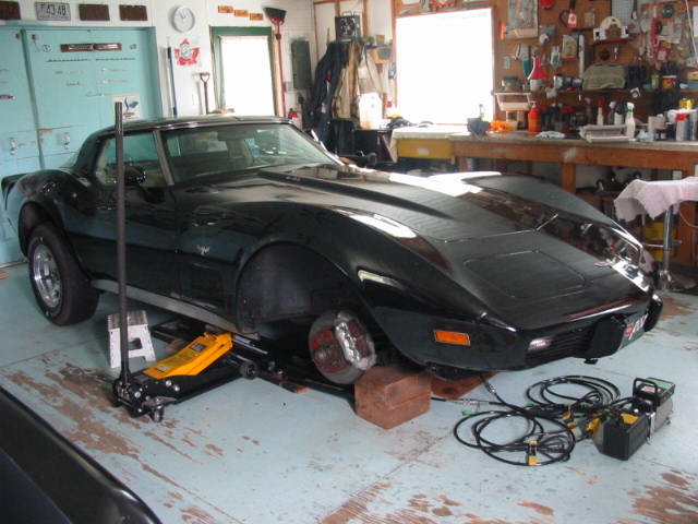
As to the ’79 Corvette, it is laid up. One of the new Firestone tires developed a bubble in the inner sidewall and went flat. More on my dealings with Firestone/Bridgestone later.

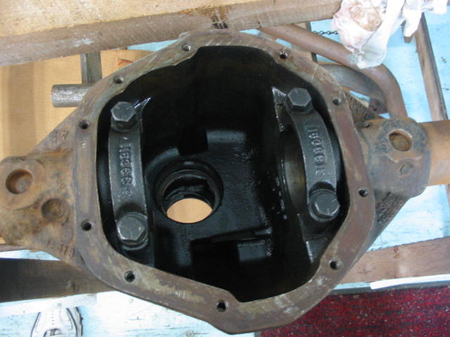
I am beginning with an empty pot. This unit originally housed a positraction unit.

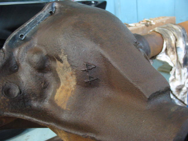
Proof positive that this housing is for Dana 44 units.

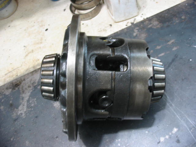
This is a Dana 44 posi unit. Very similar to those used in the Corvette differentials. It is a used unit and needs to be opened up and checked. I can’t remove the bearings until I get the special pullers for the job.

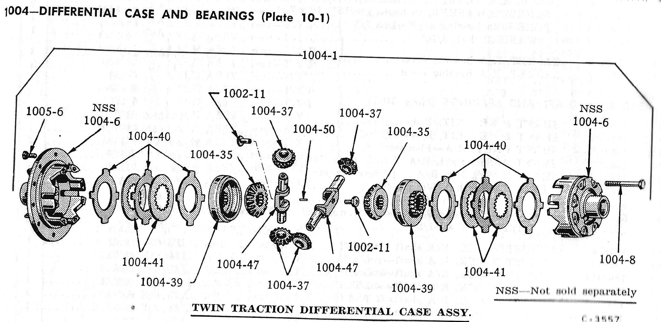
This is the parts book illustration from the Studebaker manual – they called their positraction units Twin Traction. The plates on either side need to be checked for wear.

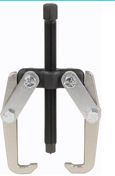
This is the correct puller to remove the bearings and shims from the positraction housing. With to bearings removed the unit can be disassembled and checked. I picket up this unit from Amazon for CDN$124. A lot of money for a puller, but it will prove it’s worth as the bearings may need to be removed and replaced a few times to adjust the shims to give the correct wear pattern on the crown gear.

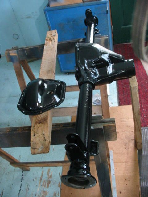
Black is best! After a good cleaning – last with paint thinners and a tooth brush – it’s been coated with Tremclad rust primer and then gloss black. Tremclad seems to be fine except where the temperatures are getting up to those under the hood. I had problems with the air filter sticking to the base plate where I used Tremclad oil based rust paint.

Next: more differential details.