

Major grunge cleaned off and ready of disassembly. All looks good so far.


I used this same setup when I overhauled my Studebaker Bendix pistons. It is the nicest way to get the old seals out. You pick the fitting that retracts the piston and rod, apply pressure and the seal and retaining washer pops out 🙂
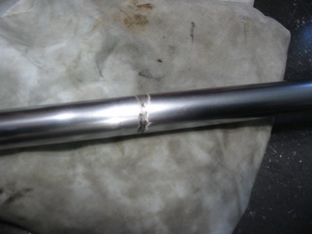
Oh boy! This is a show stopper for the PS piston. A rust groove about half way around the rod, 1/8″ wide and a few mil deep. Bad news, but on the good side it explains why the system was emptying the pump reservoir.
Fortunately the pistons are readily available and so I have put in an order for a new one from Corvette Depot in Windsor, ON.

Now for one step ahead – the pulley kit also nicely pushes the pulley back onto the shaft. No way should a press be used as it will likely damage the internals.
Next: clean up and paint -steps forward.


