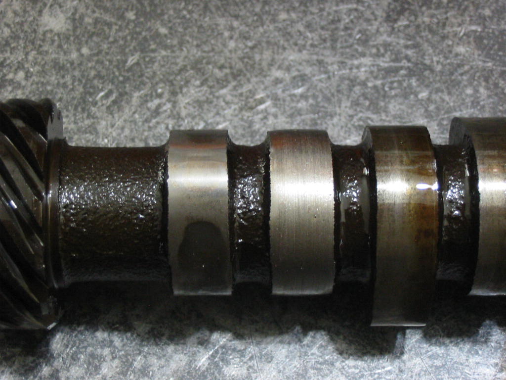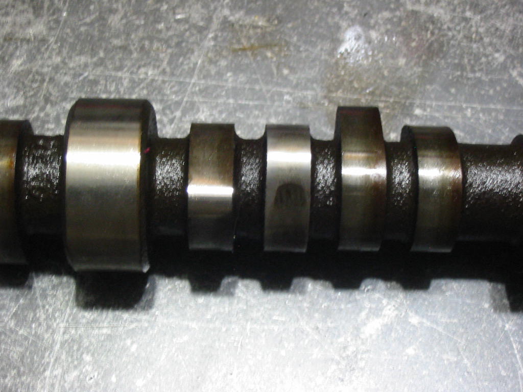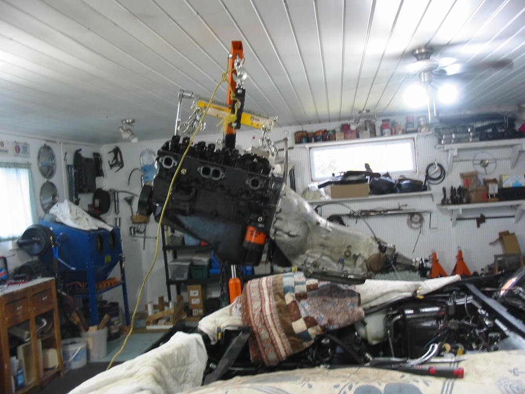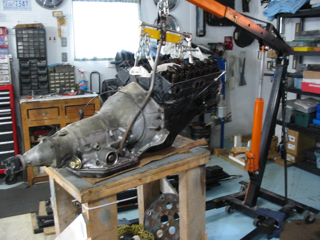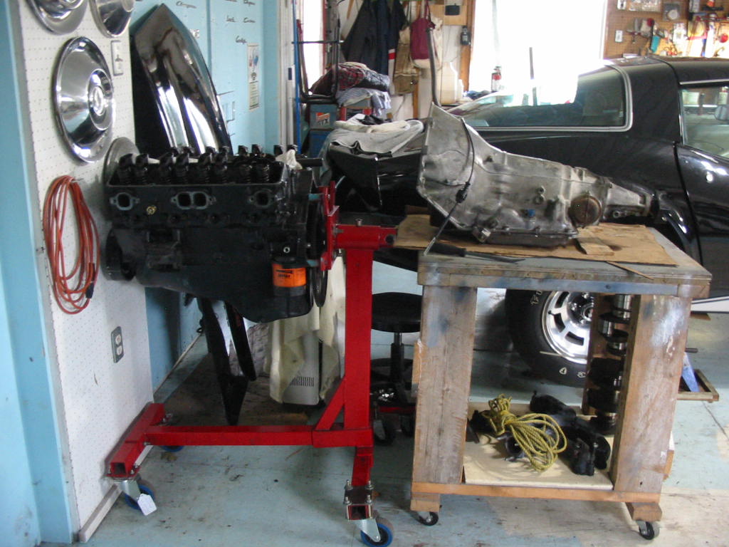
350 Tear down #4

Cleaning up the head bolts with the wire wheel. The manual says to coat the threads of these head bolts with thread sealant. By the looks of them the builder dipped the whole bolts in the sealant – what a mess to clean off.

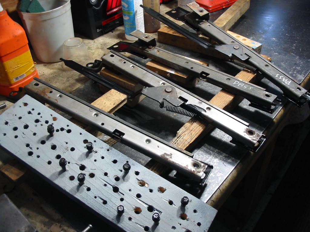
Some parts like these pan bolts I put in parts solvent and then sand blasted them before painting. I find these boards with various size holes handy to hold bolts and screws for painting.

Lots of parts to clean and some to paint. I’ll hold off painting things like the timing chain cover and pan until the engine is all together. Then I’ll give it all a good coat of GM corporate blue which is it’s original colour.

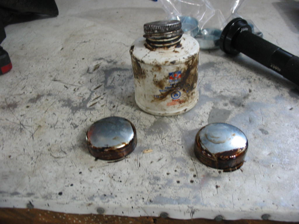
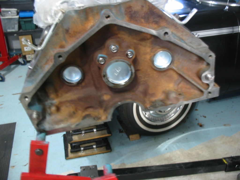
I cleaned out the residue from the rear seal using a wire wheel on my drill. I then used a dental scraper to get the remains out of the edges.

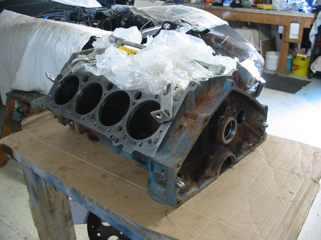
I’d have liked to put the pan in the sand blaster, but there is no way I could be sure that the all the sand was out of the inside under the baffle. Silica sand in the oil pump would not be good!

A bit of time sanding and cleaning and it’s ready for paint. I cleaned away the ‘shellac’ deposits using a scotch brite pad and some solvent.

These went through the sand blaster – thankfully because the timing cover was quite pitted and the harmonic balancer has some rough casting areas.

Lots of bits and pieces to be cleaned and painted.

Look so much better with a coat of primer. Some parts will stay in prime until they are put back on the engine and the whole painted in GM corporate blue. Others will get a couple of coats of satin black.

Next: Big problems and as the saying goes ‘the best plans of mice and men…’

350 teardown #1

I’m a little out of sequence here. I meant to post this as the first in the series on the engine rebuild, but…..

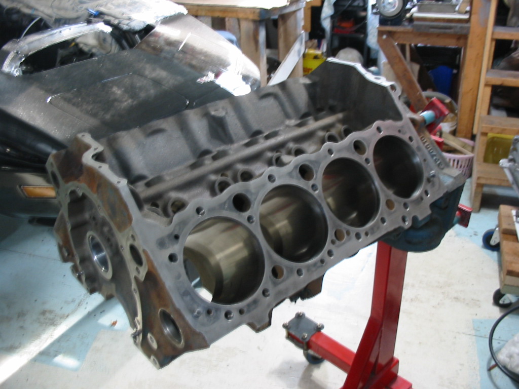
Time to tear down the original 350 and see what needs to be done.

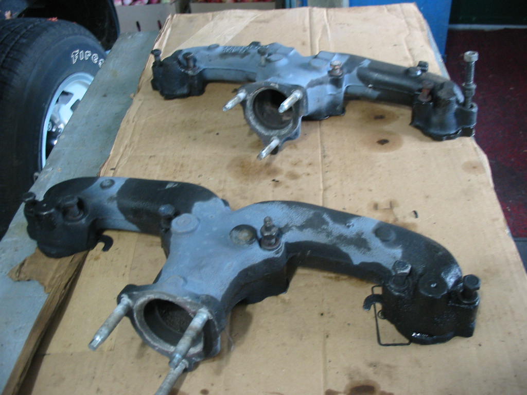
The original manifold will be replaced by an Edelbrock high rise – now on the 305 in the Chevy. I will keep it for whoever buys the car just in case they want to go back to the original intake setup.

The lifter valley looks nice and clean. Not much in the way of sludge. I did run some Seafoam cleaner through the system and that may have helped. The rust colour is not rust, but the reddish oil deposit from heated oil on hot engine parts.

Looks like all the cylinders are firing pretty good except for the one on the back head, far right. These heads are GM462824 units. They are the light casting type. I don’t want to go through the whole process of doing a valve job and magnafluxing only to have them split sometime down the road. I do have a set of Mexico GM88417368 crate engine units with the same 76 cc combustion chambers and the same valve size. I’m planning on using them.

Lots of carbon and there is actually a chunk out of the intake valve (arrow).

Turns out it was another intake valve that was burnt (leftmost valve) and causing the continuous misfire that was so irritating. The next one was chipped, but seems to still be firing. The next valve shows that the valves were working their way into the head. Likely caused by high speed driving with unleaded gas – ’79 heads did not have hardened seat areas. The exhaust valves show a lot of carbon (far right). Not sure why

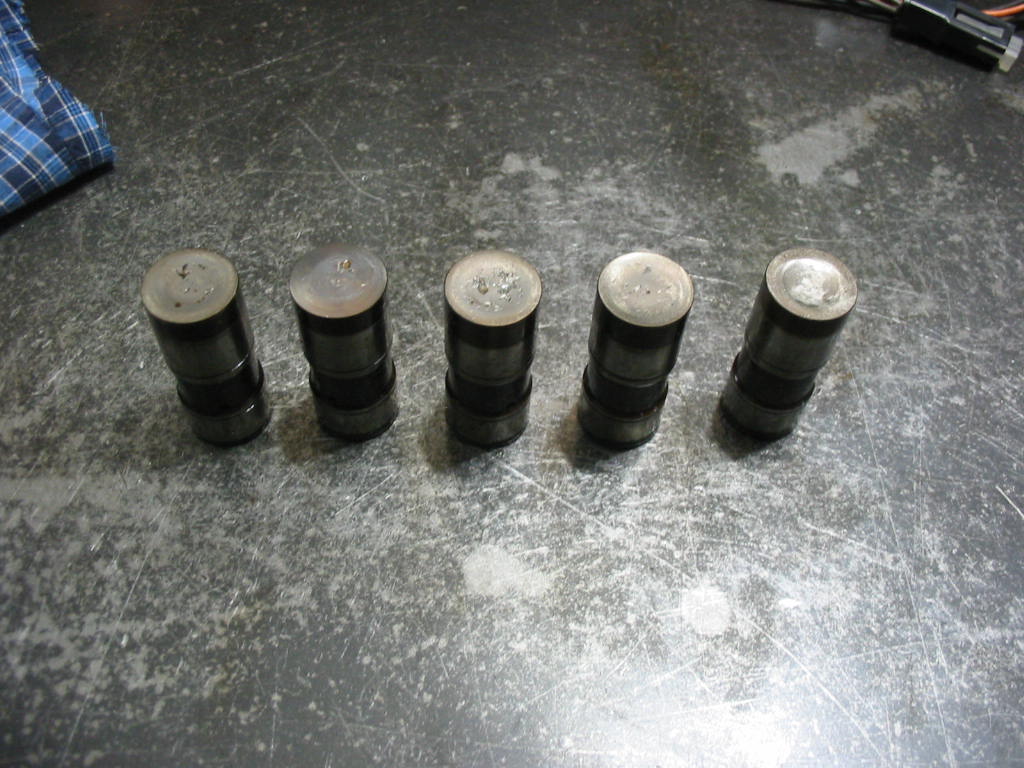
I’m keeping all the push rods and lifters in order just in case…

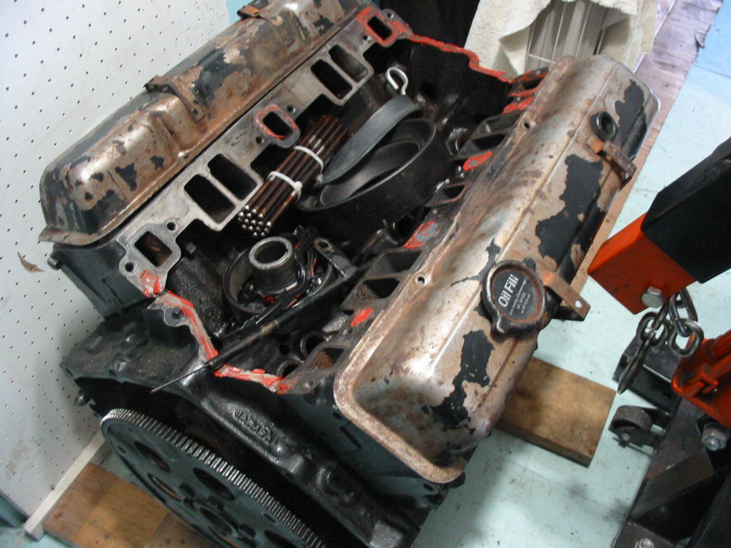
Pan off and all looks OK so far.

Harmonic dampener and timing chain cover off revealing a somewhat stretched timing chain.

Next: more on the tear down.

350 teardown #2

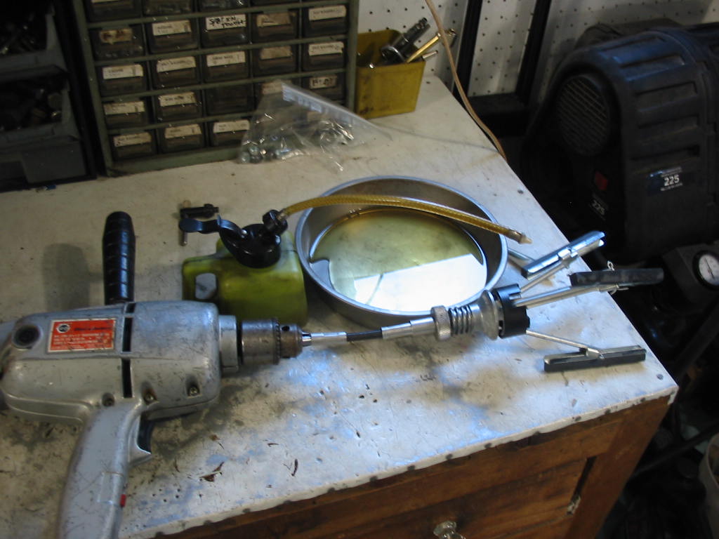
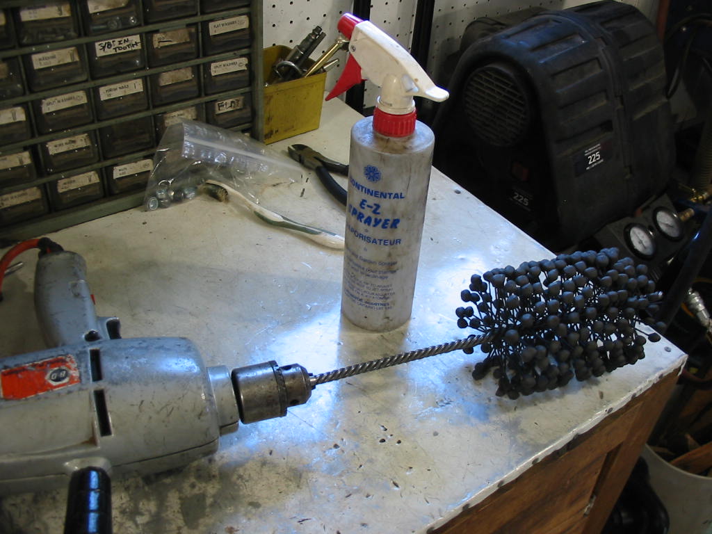
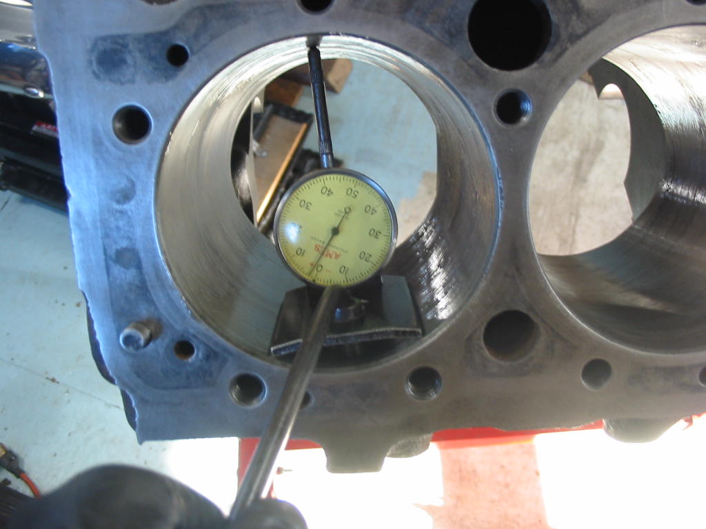
Ready to use a reamer to remove any top-of-cylinder ridges so I can get the pistons out. The paint wheel on the drill was good to remove any carbon deposits at the top of the cylinders -without damaging the cylinder wall – so I could see how thick the ridges were.

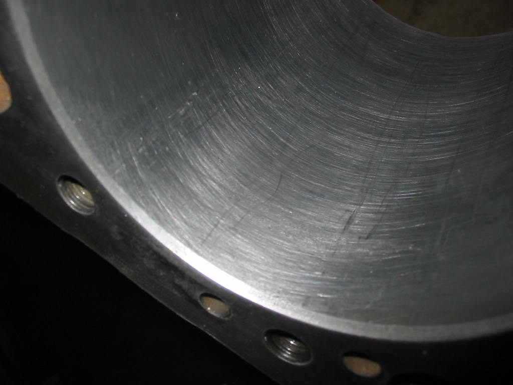
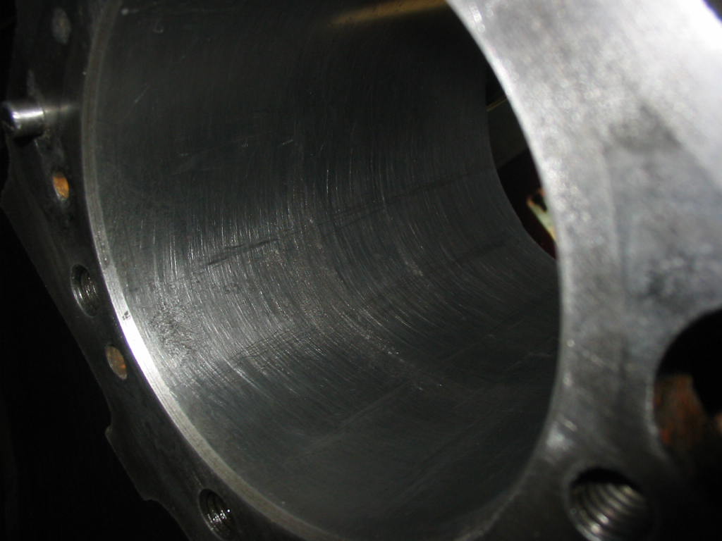
Surprisingly for an engine that is supposed to have 150k km on it there was virtually no ridges at the top of any cylinder. All the pistons came out easily once the carbon was removed with the paint stripping wheel.

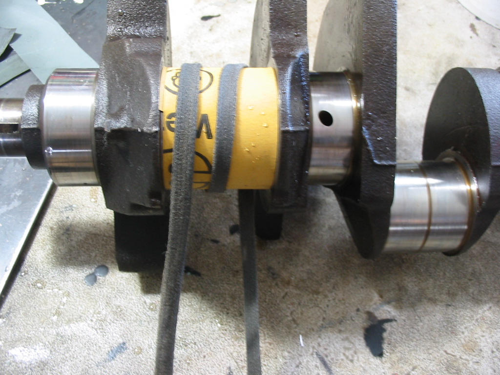
Old trick I learned years back is to put small lengths of rubber hose on the exposed rod bolts so they don’t accidentally gouge the crank journals as they pass by.

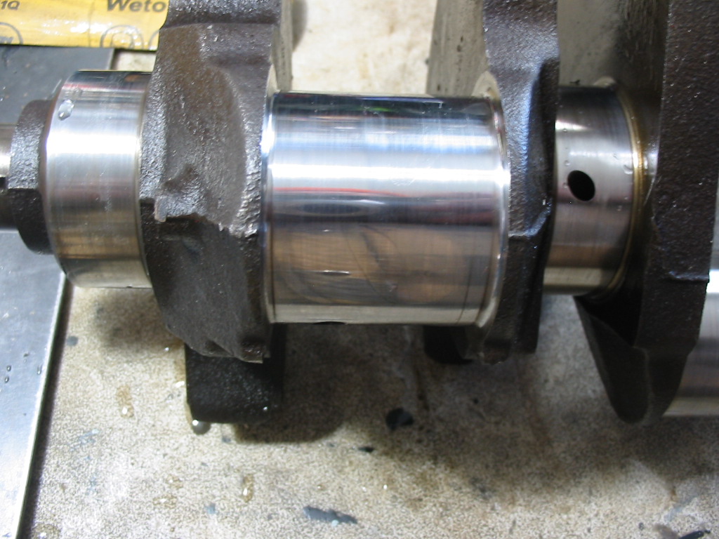
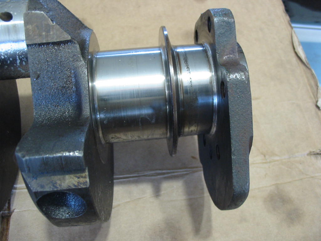
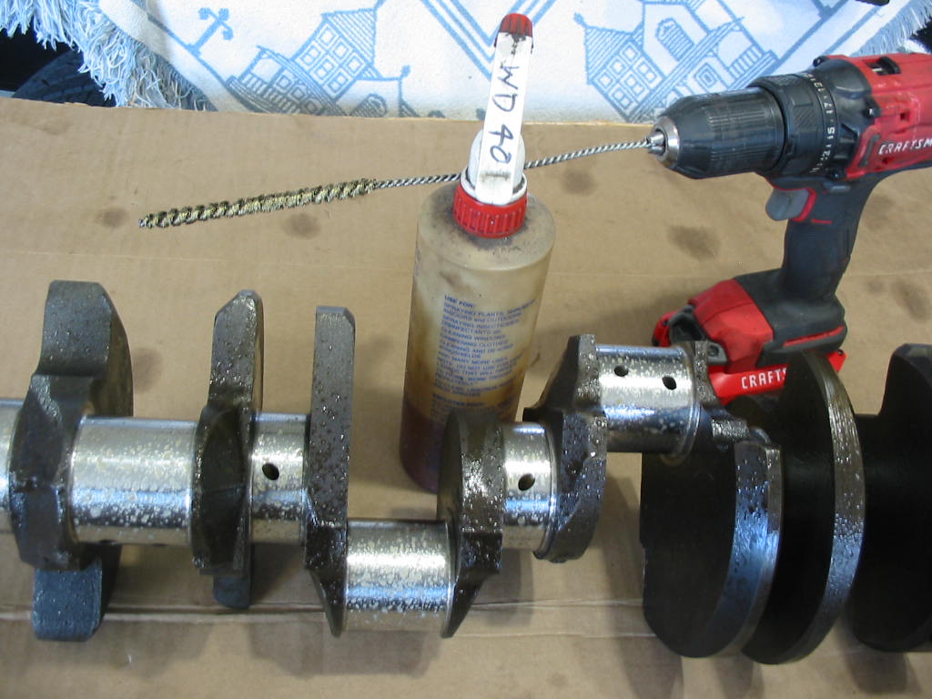
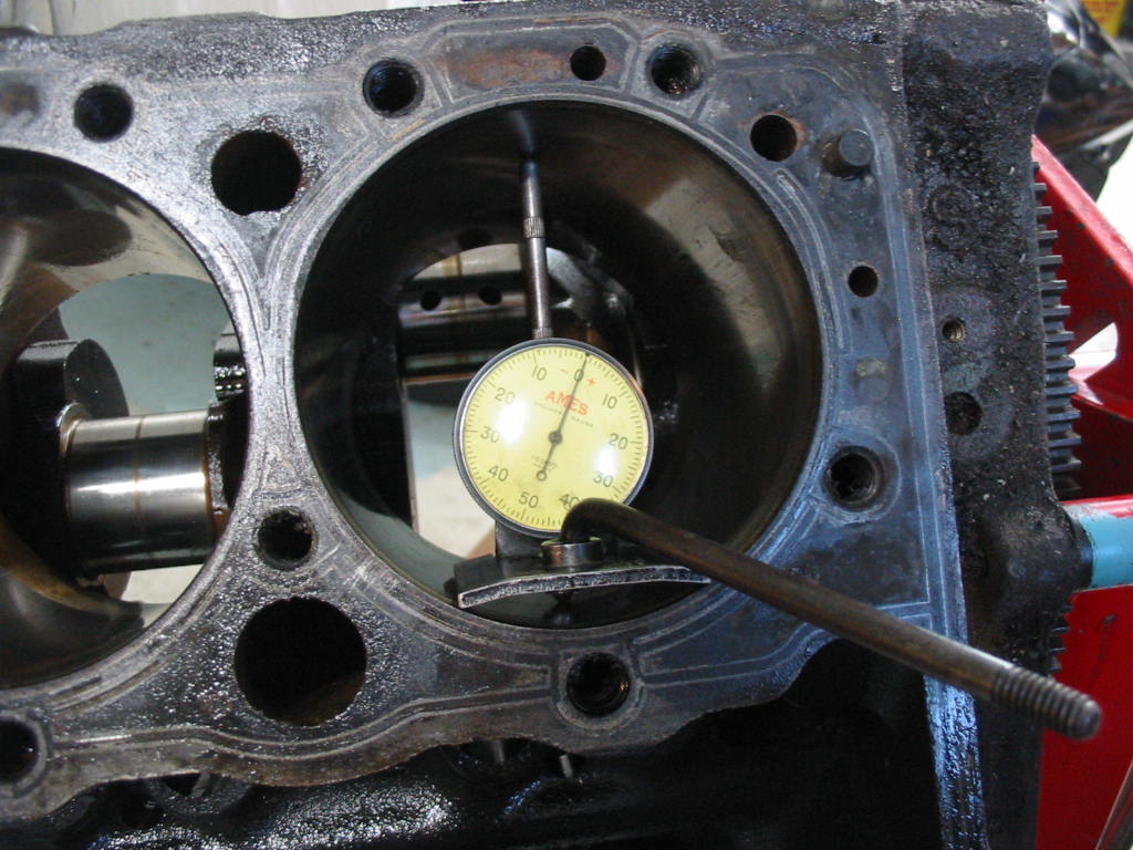
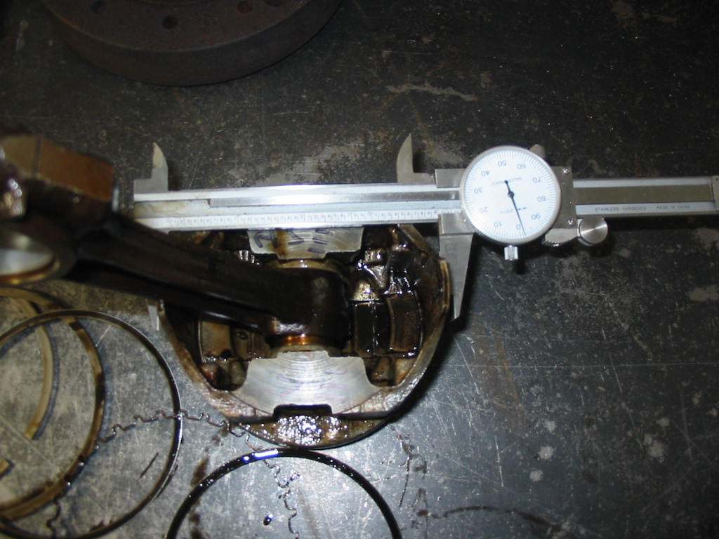
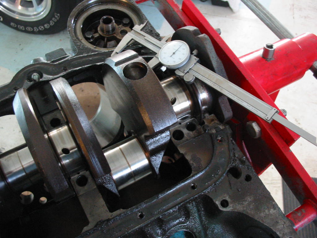
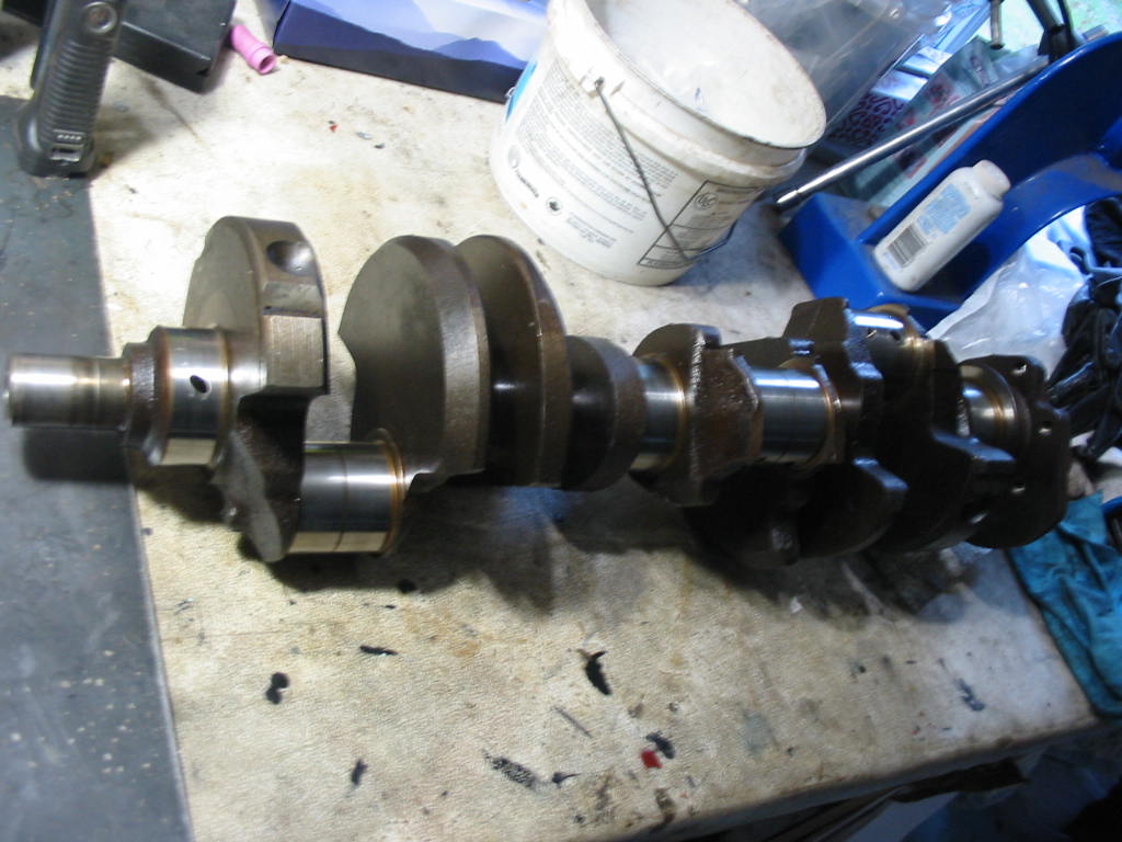
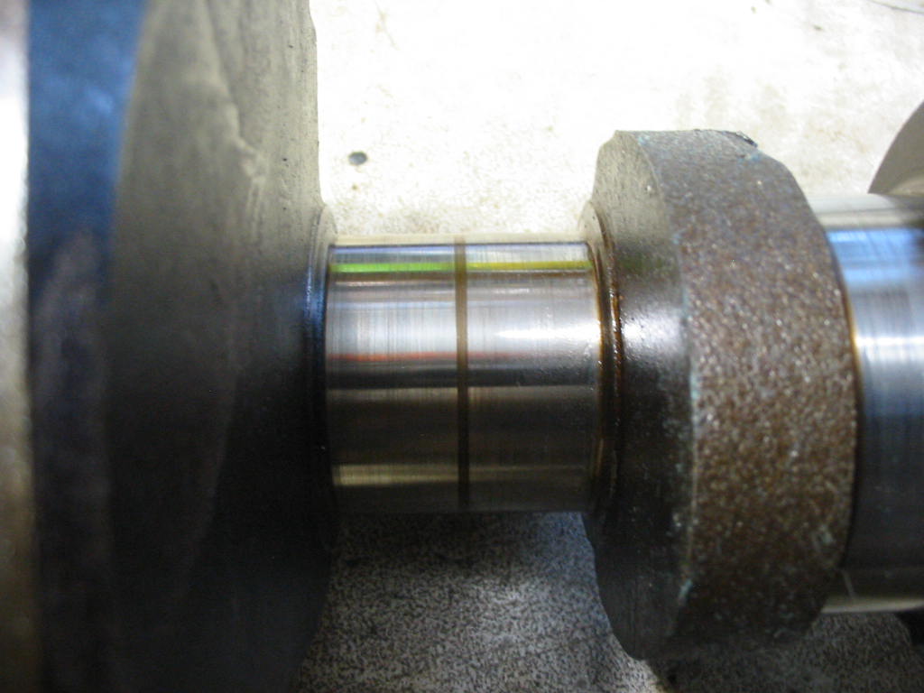
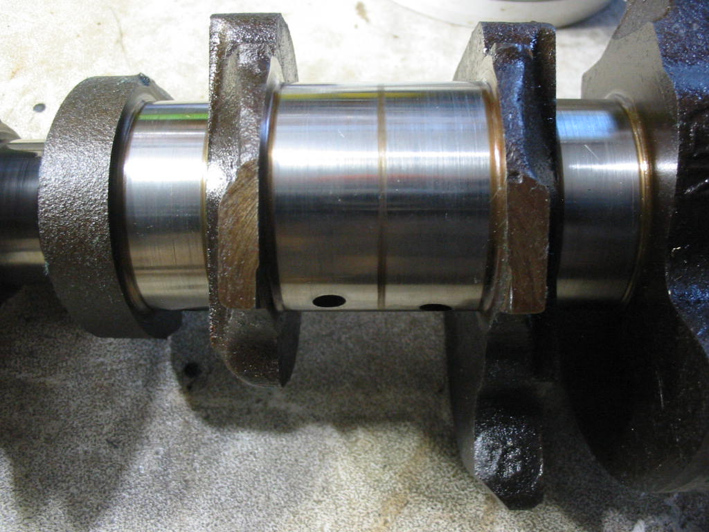
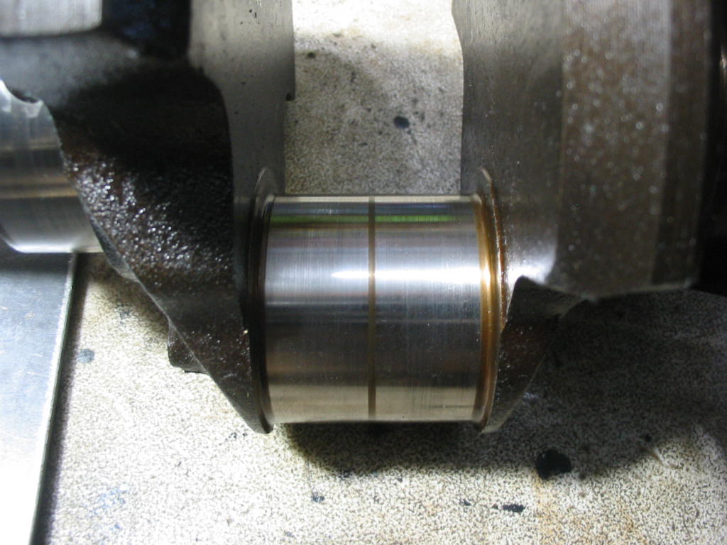
The crank journals look nice with just a bit of normal wear. I should be able to clean them up nicely with some 1500, 2500 and crocus cloth. I still need to do the measurements to see what I’ll need by way of rod journals and mains.

Next: more teardown and breakdown.

Recap – choke vacuum break

Turns out my little bend in the vacuum break arm didn’t do the trick in the end. I actually neglected to adjust the choke break when I put the carb together – funny I should have missed that.

The instructions in the shop manual require a special tool to set the choke brake. This is something I don’t have and so may have put off setting it up till later….

Fortunately I have an old Peterson’s manual from the era and also the old carb from the ’82 Caprice. The manual instructions didn’t require any special tools and a careful inspection of the setup on the old carb gave me an idea of what to do.

The only fuzzy area was the setting of the choke flap with vacuum put on the choke break. I don’t have the carb number so I couldn’t get the exact size for the opening at the front of the choke flap. Looking at the old carb and the numbers in the manual for all the Quadrajets I settled on 1/8″

With the choke brake adjusted the actuating arm (now back to straight) clears all the linkage.

With the engine started the vacuum break opens the choke properly.

A few minutes later the electric choke allows the choke plate to move to the fully open position.

Next: Even though there may still be a few bugs to work out it’s time to start the work on the original 350.

Getting the bugs out

The alternator isn’t behaving itself. It shows 13+ volts when starting out, but as the engine heats up it drops the 13 and below. I have the 56 amp alternator from the ’82 Caprice. Buddy Don ran it up on his test machine and it seems to be OK and the bearings are fairly quiet. The regulator connections were a bit rusty and it’s hard to clean them in place so I opted to take the unit apart and clean up all the contacts and the corrosion on the case. The nuts and screws needed a bit of penetrating oil so they would come off easily without damaging the diode unit or regulator. I also added a tad of wheel bearing grease to the needle bearings in the back of the case.

Cleaned up the front half of the unit and then fit it back together.

All nice and finished and ready to go. Sadly it wouldn’t generate from the get-go 🙁

In talking to Don I remembered a side comment he made about someone changing the GEN light bulb in the dash. I then realized that I must have changed that bulb for a diode bulb when I replaced all the dash lights. The diode is on the left and the regular incandescent is on the left. With the key in the ON position I was getting a reading of about .55 volts at the R connection on the alternator (the two prong plug that goes to the alternator has a F (field) and R connectors). This is apparently not enough to trigger (excite) the alternator to start charging. After I changed the bulb I got a reading of over 2 volts and that was enough to get the alternator charging. Now there was a full 12+ volts at the R connection and the GEN light on the dash was out.

The Caprice 56 amp alternator in place and working fine.

My second problem was that the choke flap wouldn’t close when I pressed the accelerator with the engine cold. I finally traced it down to the aftermarket vacuum dash pot. The linkage was getting in the way of the choke linkage. Just enough to hold the choke open until you fiddled with the choke arm.

The solution was to put a wee bend in the arm to keep it free. Once this was done the electric choke mechanism moved smoothly and the engine started and warmed up nicely.

Next: if there are no more bugs it’s time to start tearing down the original 350 🙂

Test drive time

Old thermo fan installed. We’ll have to see if it is more quiet than the flex fan.

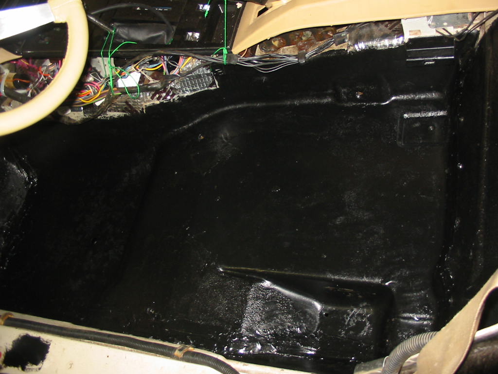
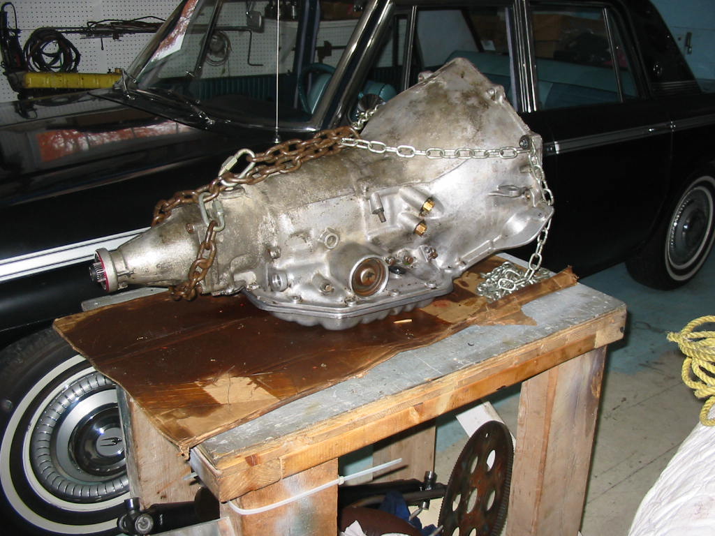
This is the speedometer gear on the original ’79 TH350. I’ll be moving it to the ’83 TH350C when I swap back the original engine in the winter of ’26/’27. Until then I’ll live with the incorrect speedometer reading. It’s roughly 20 kpm fast. It’s too much bother to re and re the driveshaft and trans tail shaft housing and all the underneath work that involves, but I’ll see how the work goes this winter. I have a number of upgrades for the ’66 Stude and not too much on the Chevy except for fitting in the Caprice cassette radio and maybe getting the floor covered with sound deadening material. Oh yes, and getting the seats re-upholstered, installing a new condenser and getting the AC operable. Not to mention the rebuild on the old 350!

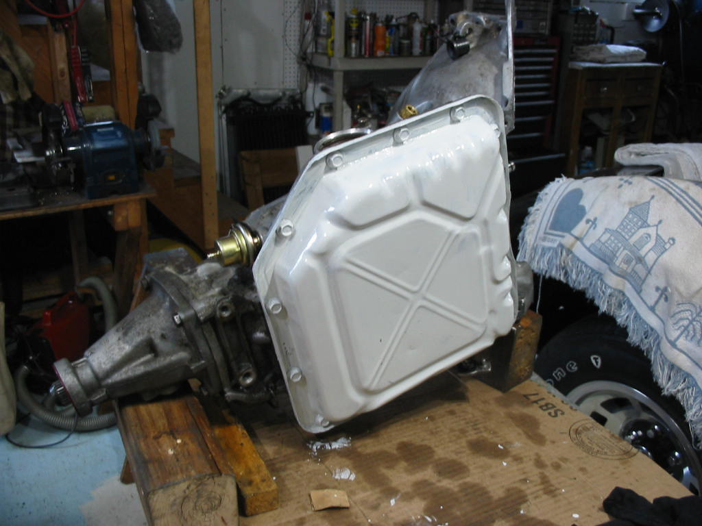
Trans case clean-up finished.

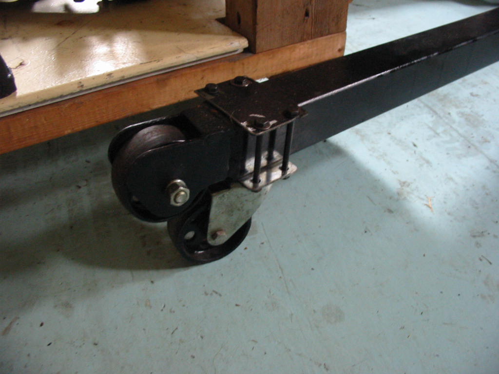
Built a little dolly to move the trans easily. A bit of a grunt getting it off the work-bench and onto the dolly. I actually put it on my pneumatic work seat and then lowered it to the bottom and then slipped if onto the dolly. Can’t be too careful at 79. The back isn’t what it used to be. I”ll tuck the TH350 trans away – just in case…

A very successful test drive. The lock up converter works OK 🙂 and the engine is running fine – the heater is also working fine now. I had mistakenly attached the its ground at the starter to the starter solenoid connection – wonder I didn’t blow something up! And the engine is a whole lot quieter with the original thermo fan. So I’ll buy a new thermal unit, paint it up and use it.

Next: more bugs.

Onwards…

I finally put two-and-two together and figured out that the trans from the ’82 Caprice is a lock-up converter model TH350C. It has a different input shaft and a special lock-up valve body red arrows. Something I will have to test out. If it works OK I will keep this trans when I swap back the original engine. So now to find the parts needed to hook up the lock-up and have it automatically cut in and out 🙂

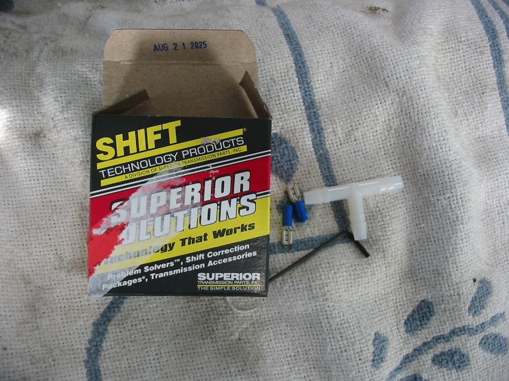
I was very fortunate in that the Caprice is still available and I was able to find and remove two important components for the lock-up torque converter. The item on the left is a vacuum switch and the round thingy on the right is a vacuum delay switch which stops the transmission from rapidly going in and out of lock-up. There is only one wire coming from the trans so I’m not sure where the extra output wire is supposed to be connected to. More Googling to find that out as I don’t have the wiring diagram for an ’82 Caprice.

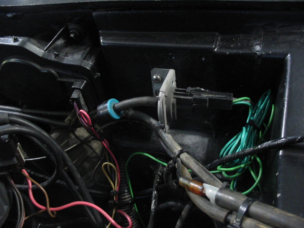
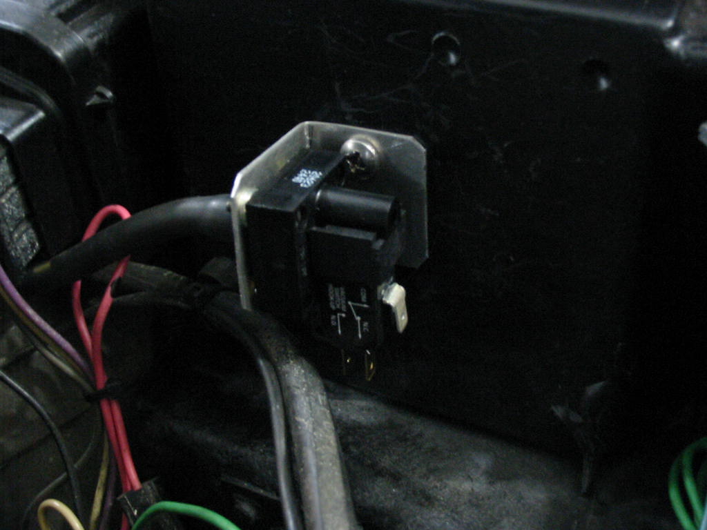
I found an open spot on the firewall and got the vacuum switch and the delay mounted. The harness from the Caprice has two wires exiting from the vacuum switch. I’m not sure what the second if for so I’m leaving it wrapped up until I see how the lock-up works.

One of the problems with the last test drive was a very loud whirring noise from the engine that got louder as the rpm increased. I’m thinking it is the flex fan which surprises me since I have used them in the past and they have tended to reduce noise. Anyway I’m going to install the old fan and see if that makes a difference. I’ve cleaned it up a bit, but I’m not sure that the fan clutch is working OK. It does have some resistance, but there was signs of oil on the shaft.

Next: the next test drive will show if the fan and lock-up works and if there are any other bugs needing attention before it is ready for the next driving season.

Bits and bobs

Getting the newly painted hood back in place. I had to use this setup to allow the hood support on the left side to be loose so that I could adjust the left side hinge. After some fiddling I was able to get the hood fitted OK.
Then I tried to close the hood, but of course the new high pressure 90 degree AC fitting wouldn’t work.

Even with a straight R12 to R134A adapter the hood still wouldn’t close.

In the end I had to leave the original R12 fitting in place without the R134A adapter. I just put a schrader valve in the fitting and will put on the adapter when I need to charge the system.

First test drive and I have a bad valve cover leak on the right side. Not so much on the left, but a bit.

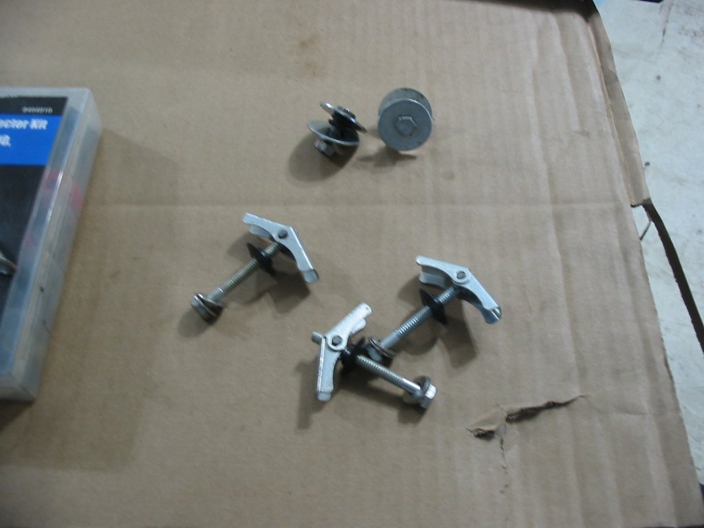
I installed a new set of Rubber gaskets thinking they were the best. Looking closely at the gasket ends I noticed that the gasket was not seating on about 2″ on either end – the black line was about as far as the gasket seated on the block. I don’t like to over-tighten the valve covers; I just tighten the screws as much as I can with a screwdriver handle and socket. I also use spreaders on each screw to distribute the pressure better.

Hard to see, but I’ve laid the rubber gasket beside new cork composite gasket (FelPro VS12869AC). The cork is noticeably thicker (7/32″). I had no leaks with the old cork units. So I have bought a new set from Car Quest is $35 – available from Rock Auto for $15 plus shipping which will be a better deal if shipping a few parts at once.

I like to coat my cork gaskets with a thin coat of aluminum anti-seize paste. Helps to save them if I have to take off a valve cover.

The charging (Generator) light came on a couple of times during the test run. I took it to my car bud Don and he was able to test it out and fix a couple of problems – rust and maybe a bad diode block.

Alternator and valve covers back in place. Almost ready for another test run.
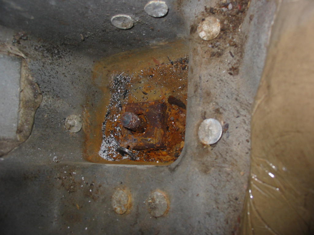
One last thing before doing another test run. The engine seemed sluggish on takeoff so I’m going to check the timing again. I have marked the original timing mark (thin white arrow) and will attempt to check it against the original timing tab (thick white arrow) just to be sure I have set the temporary timing mark (red arrow) correctly and that I have 8-10 degrees initial advance.

Next: a bit of good news on the transmission.

Last bits to do

Hood hinges back on and the hood brace in place.
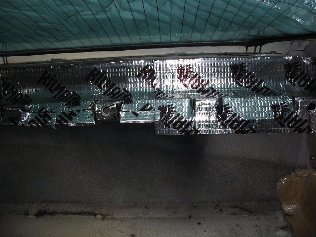
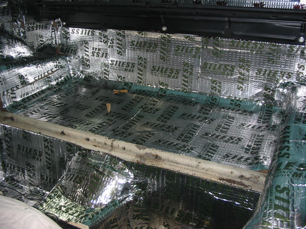
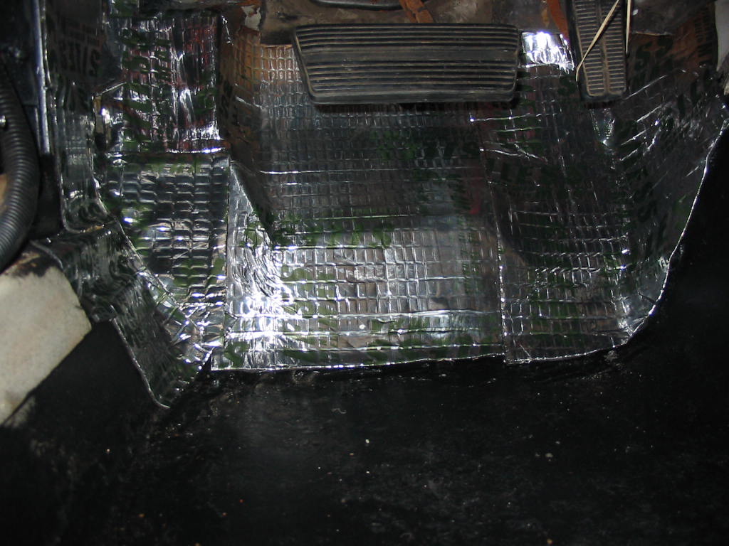
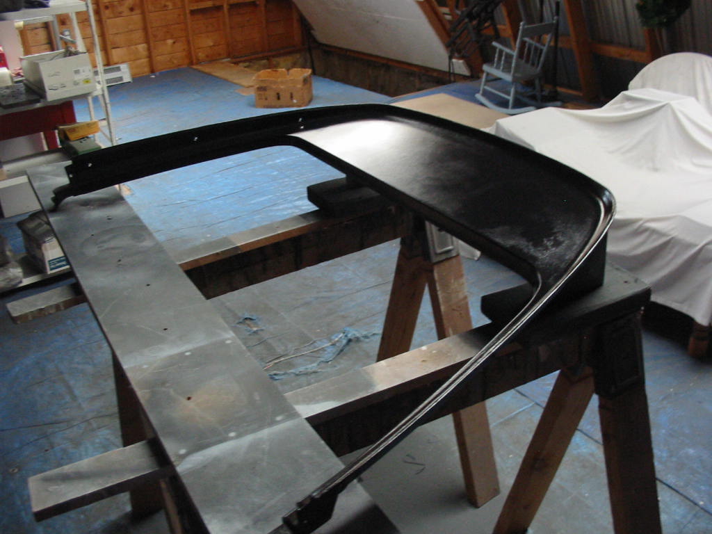
Not a fun job, but the hood needed to be cleaned up and painted. I’ve removed the sound mat attaching posts. I’ll just paint it this time and next time I’ll put on some stick-on sound deadening when I’m doing the interior floors.

Hard to get a shot of a black hood in detail. Turned out nice. Just need to hand paint some areas of the front lip and a big paint chip.

All ready for the road. Just need to check the electric choke and set the timing. I’ll go with an initial setting of about 8 degrees which will give about 27 with the vacuum advance in.

My low pressure 90 deg. fitting came in so I can check the AC system for leaks. I found a serious leak somewhere when I tried to vacuum the system. It would vacuum to about -20 and then no more. When I stopped the vacuum pump the vacuum in the system quickly disappeared.

The usual way to find a leak is with nitrogen, but I couldn’t find any small canisters of the stuff. So I opted to sacrifice some of my R22 refrigerant instead. I sprayed all the connections with soapy water before I let a small amount of refrigerant into the system.

I quickly heard gas escaping from the condenser area. It turns out that the condenser is cracked near where the lower connection is located. Can’t really get a good shot. I sprayed more soapy water in the area and the bubbling was quite evident.

So much for the condenser. Rock Auto has them for $160 plus about $35 in shipping. I don’t want to delay getting on the road so I’ll order the condenser and put it in over the winter. I’ll need to take the hood off again to get at the condenser connections, but that’s not a biggie with help from a couple of my coffee buddies.

This about ends this session on the Chevy. Still lots to do and I’ll get at it over the winter. I’m looking forward to getting the AC working, reupholstering the seats, installing the correct antenna and maybe getting some sound deadening mat over the floors and under the hood. I’m not really happy with the aftermarket radio I bought so I may try and slip in the AM/FM radio I saved from the Caprice. The aftermarket radio starts every time I start the car which is irritating and the buttons are just too small. I does have a CD drive that I’ll miss, but the Caprice radio has a cassette feature so I’m not totally lost.

In the meantime I’ll post bits and bobs now and then as I go through the fall.

More AC prep, etc

High pressure line connection to the orifice tube. The low pressure switch is a bit tight but it will work.

The low pressure line at the condenser is a bit pinched. I cured that by releasing the connection a bit and twisting the low pressure pipe until the kink was pretty well gone and then re-tightening the connection.

Ground and power leads connected with the kicker switch line travelling off to top of the photo

New throttle kicker switch in place. It will up the RPM by 100 when adjusted and the AC is on.
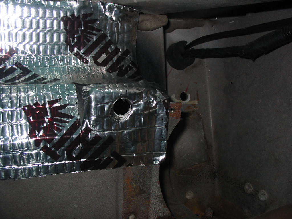
Time to tighten the rear struts. They have new bushings and need to be torqued while the weight is on the wheels. I’ve put a couple of layers of hard plastic on top of the wood blocks. This should allow the wheels to spread out and put the suspension on its lowest level.

The inner strut fastener was too close to the exhaust pipe so I couldn’t use a torque wrench. It calls for 65 ‘# so I gave it a good pull with a wrench and a wrench extender.

The lower connection needs 75’# of torque which is a bit of a bear to get in the small space for the torque wrench to swing. I chose to go to 65 ‘# and a bit more to get the cotter pin in place.
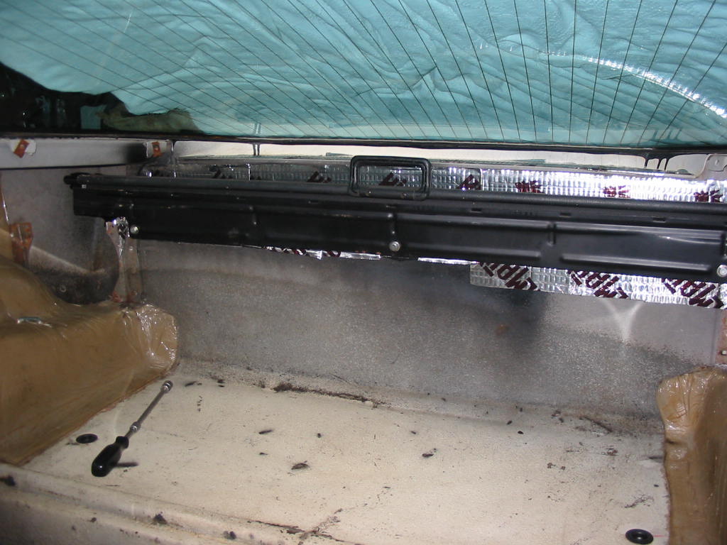
Last job underneath was to install the large ground wire from the frame to the engine block. I’ve smeared some dialectic grease over the frame contact to keep the corrosion away.
Next: Getting close to being back on the road!