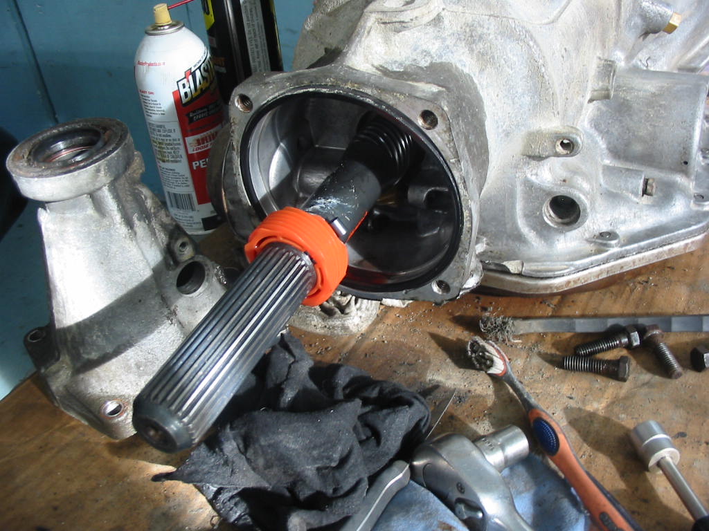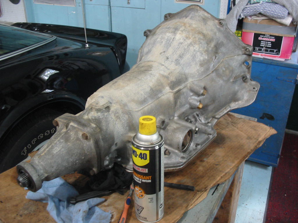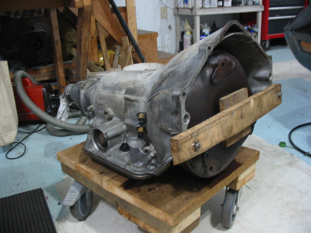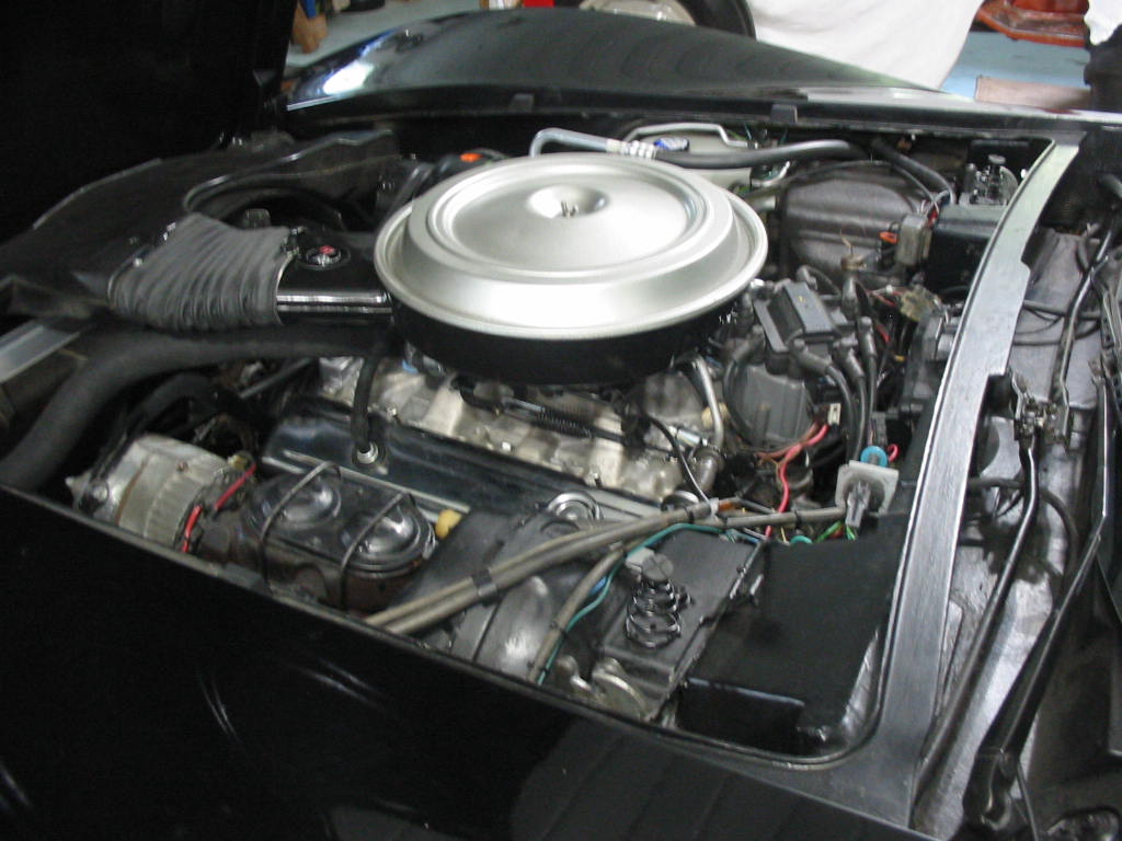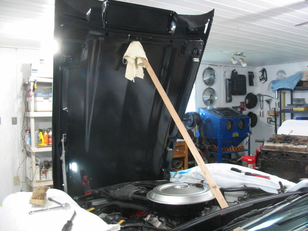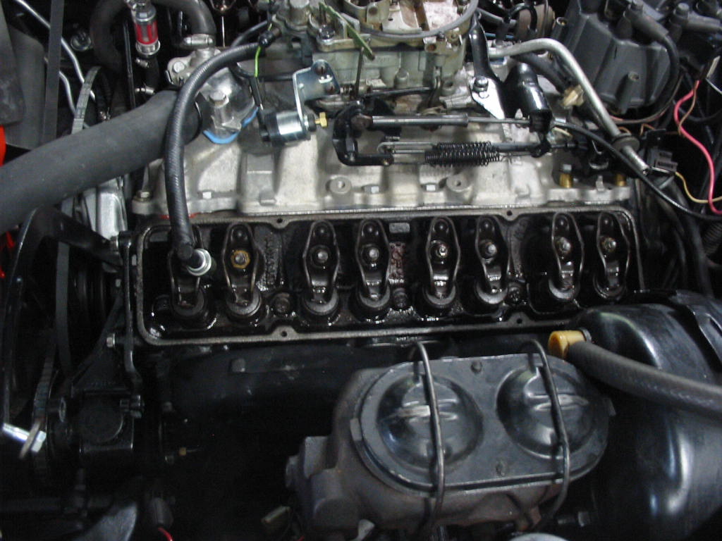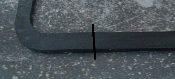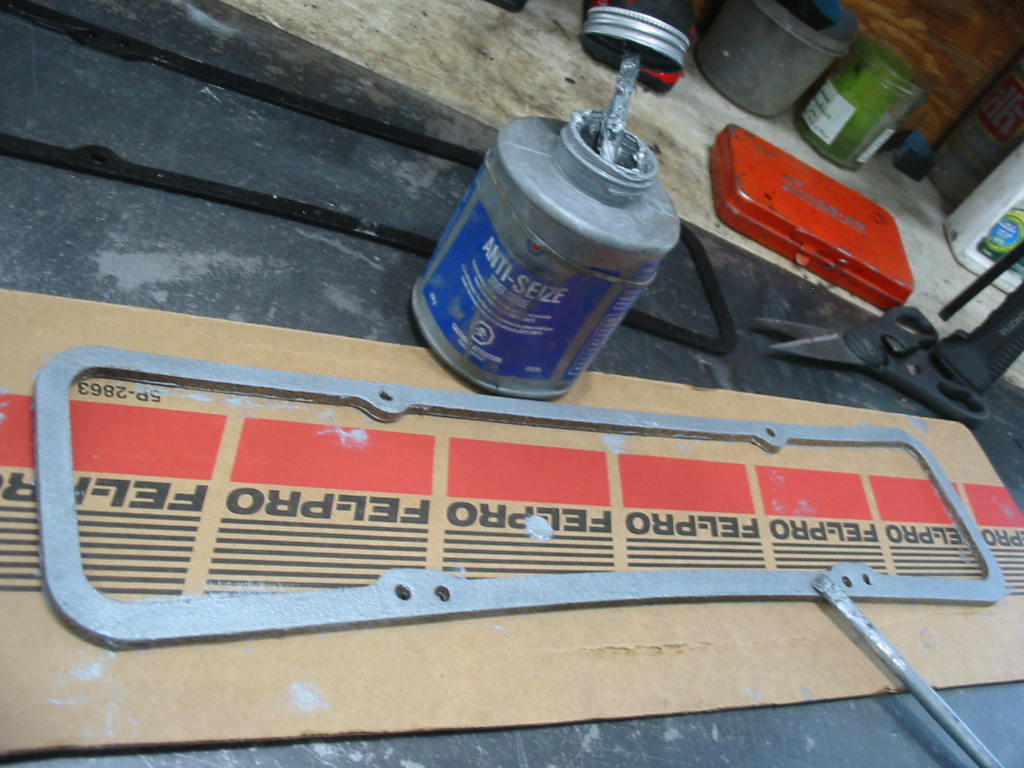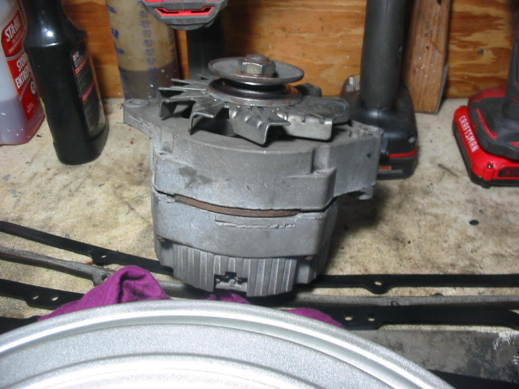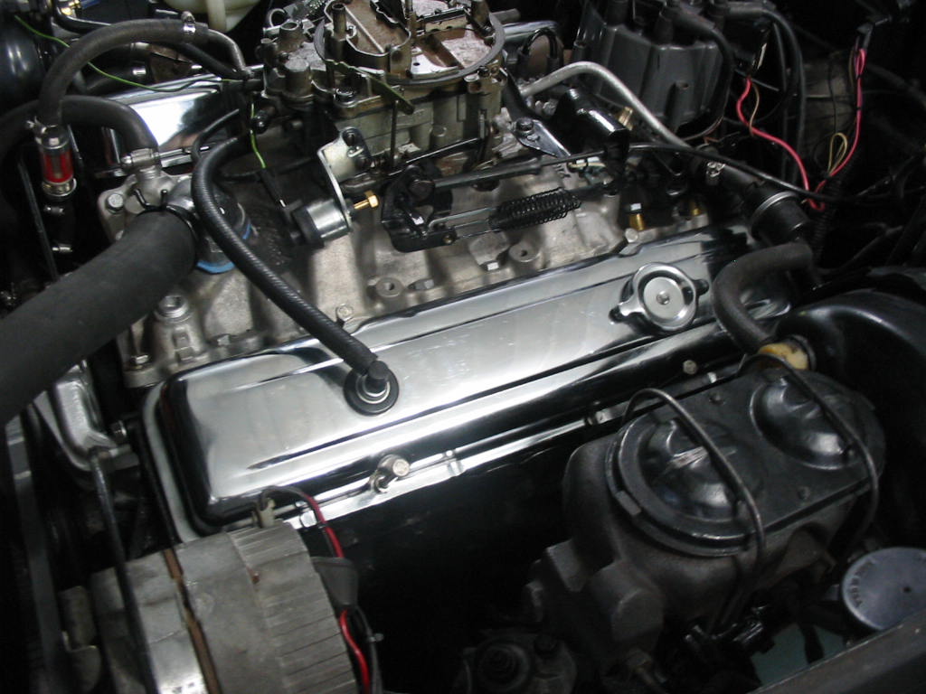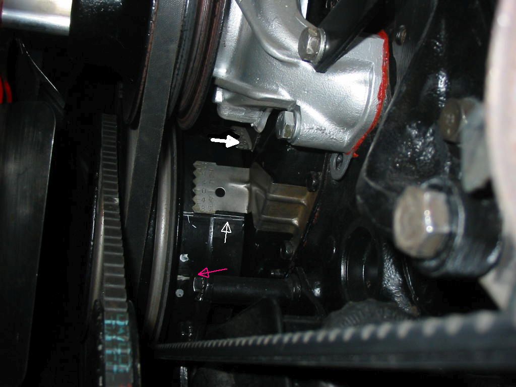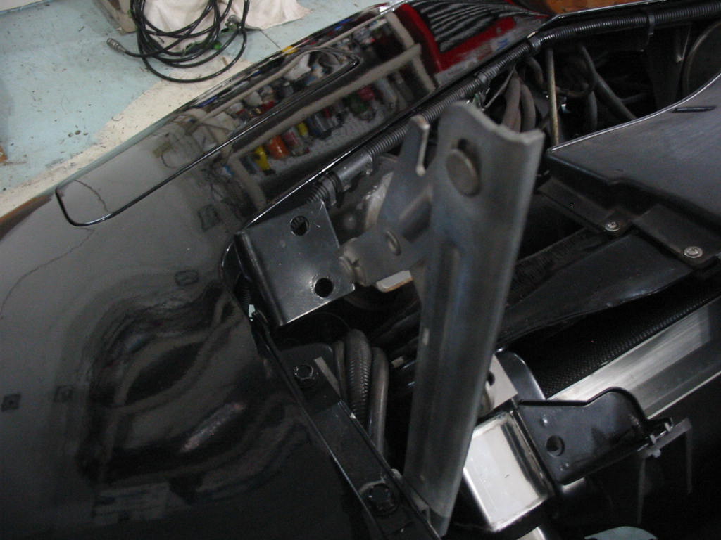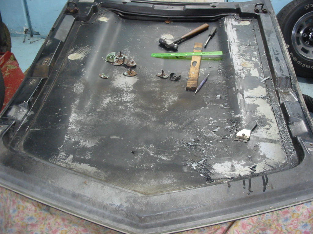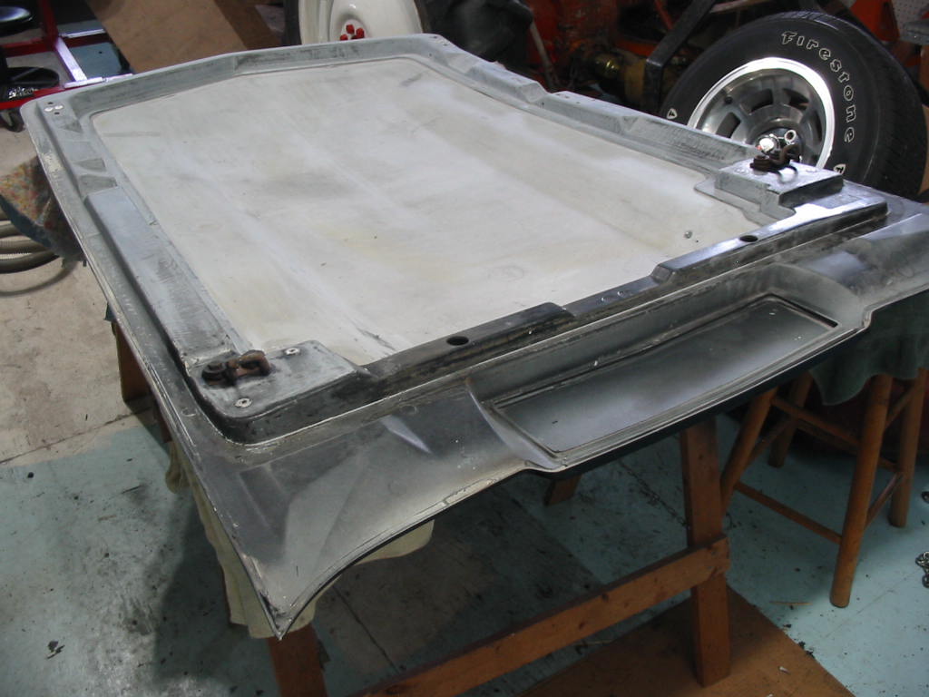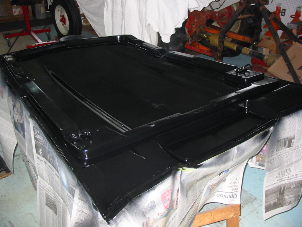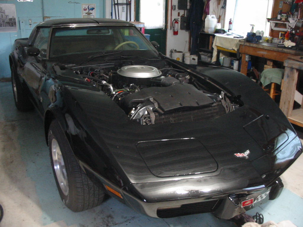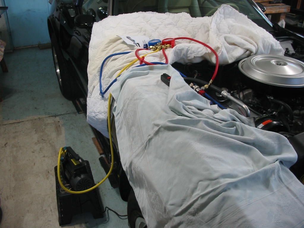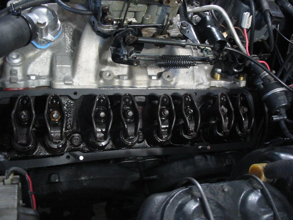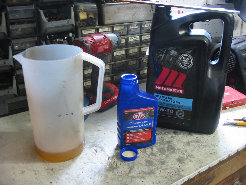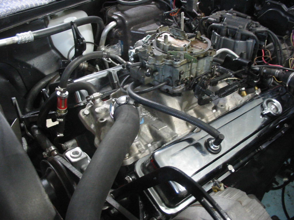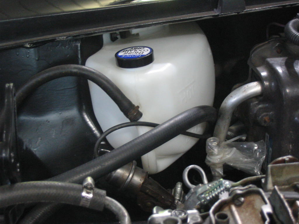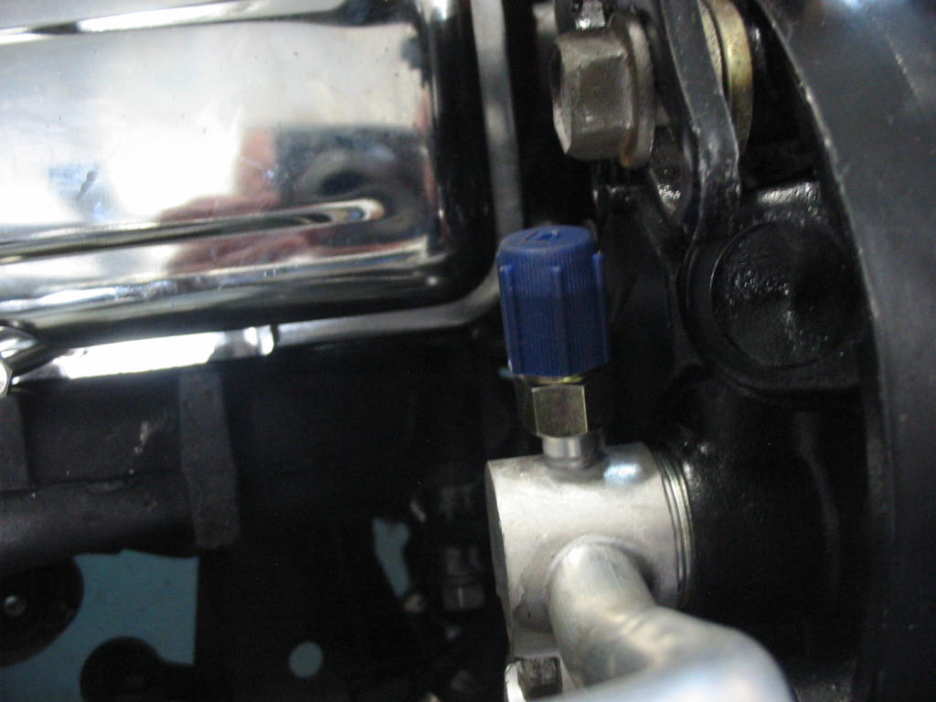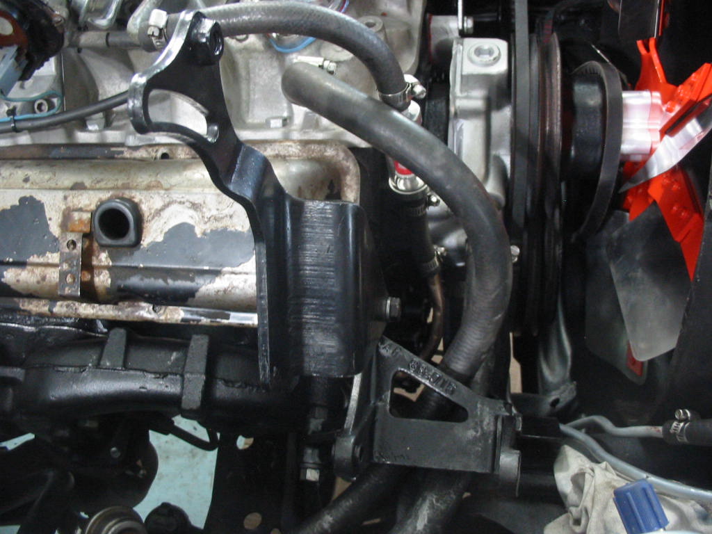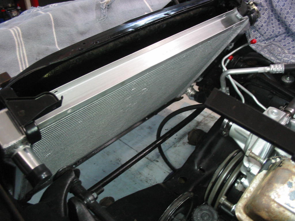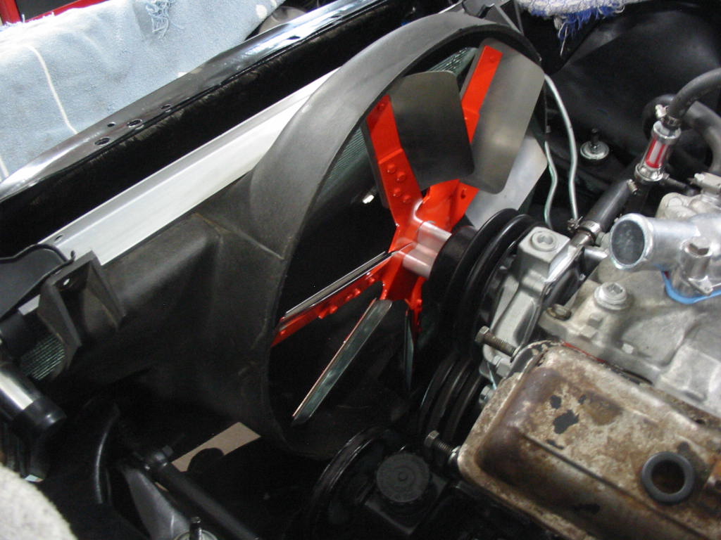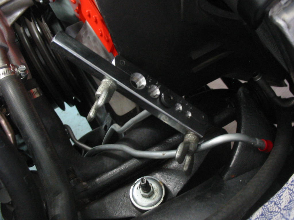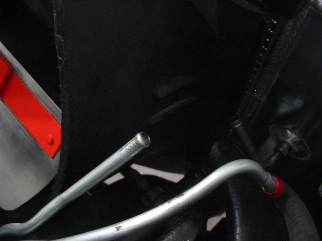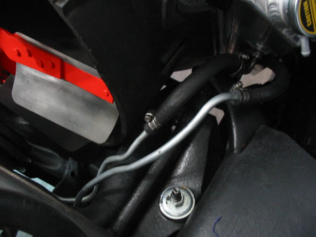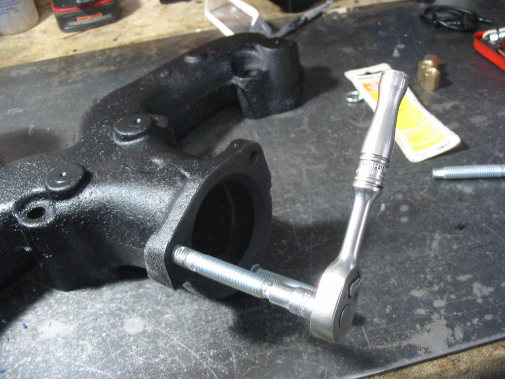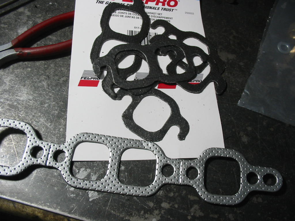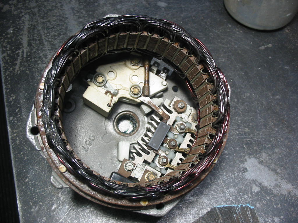
Exhausting work ;-)

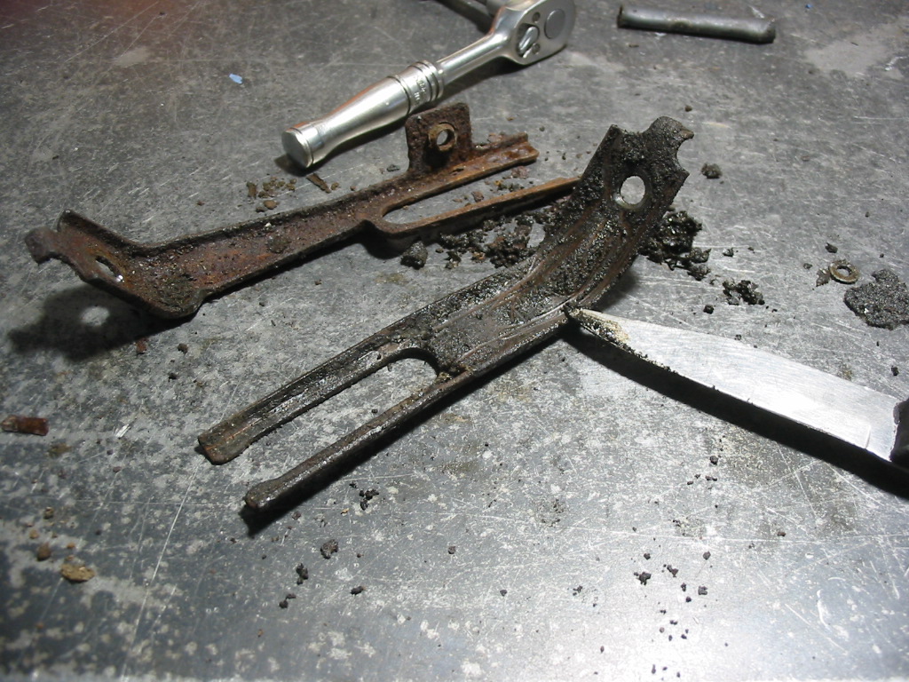
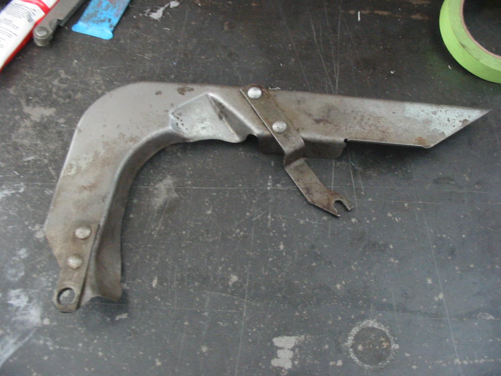
Cleaning up the plug wire guides that fit on the block behind the heads and lead the wires towards the back plugs and the wire shields for the front plugs. Same routine of scraping, cleaning, sand blasting and paint…

All cleaned up with some rubber tubing slipped on to help hold the wires firmly. They originally had a thin coating of rubber which was destroyed over time.

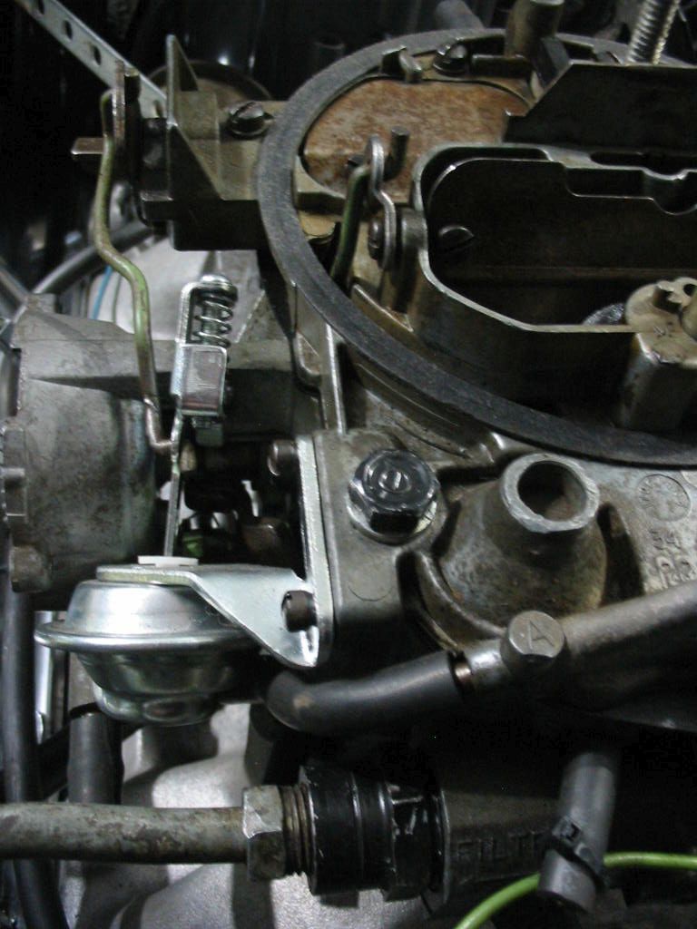
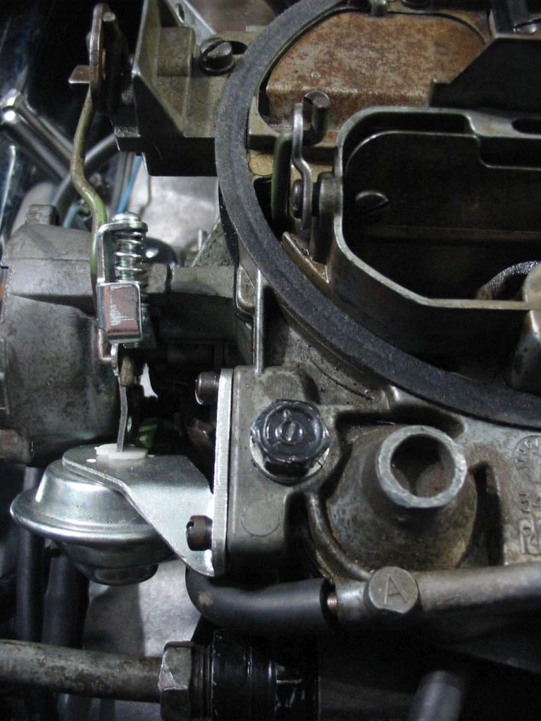
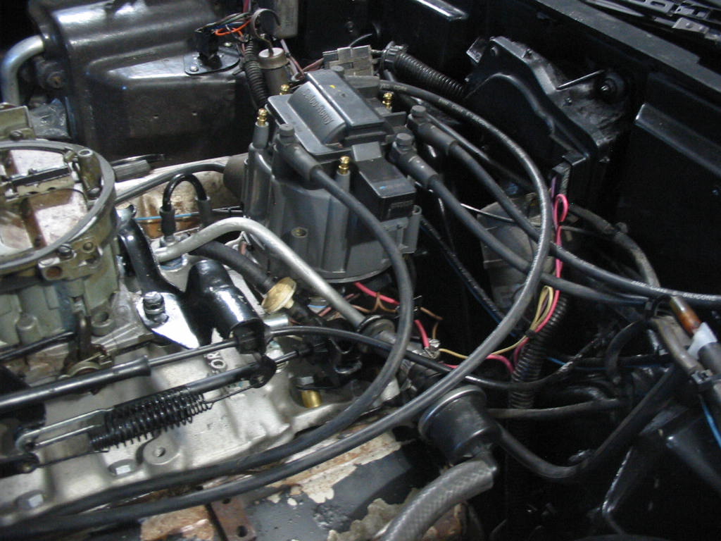
While waiting for paint to dry I’ve started to hook up the electrics. I have put on the left bank wires and will get underneath to run #1 &3 under the wire shield behind the exhaust manifold.

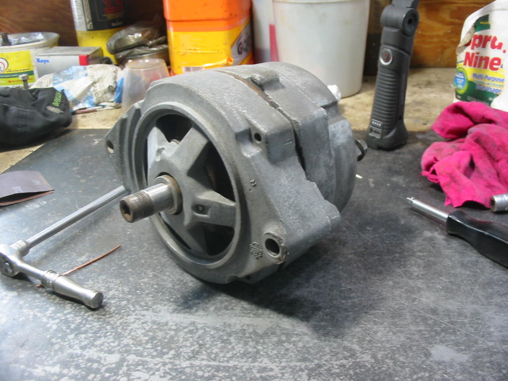
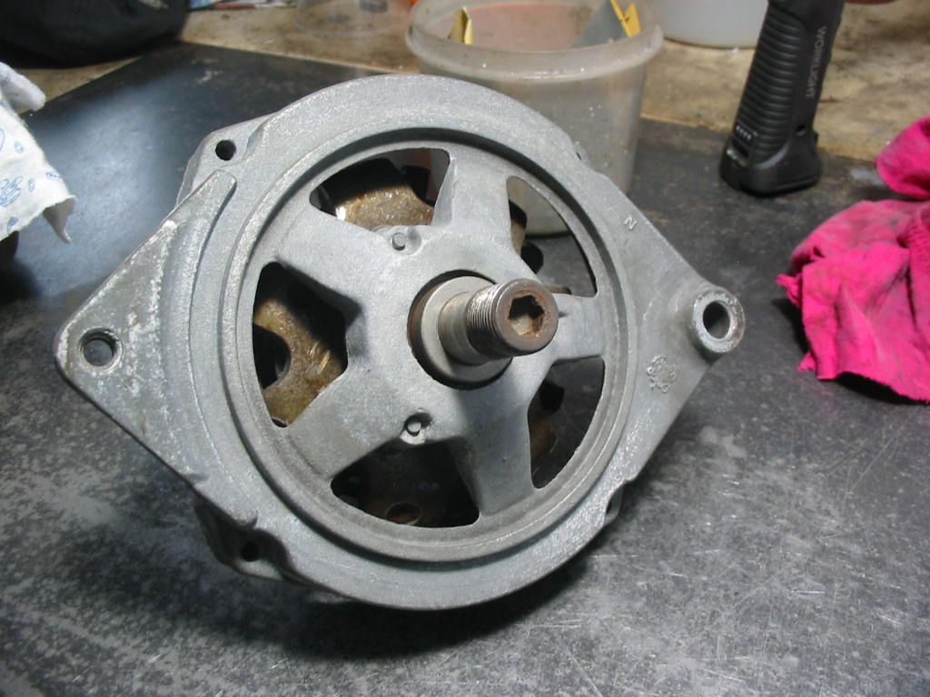
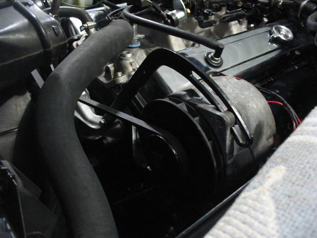
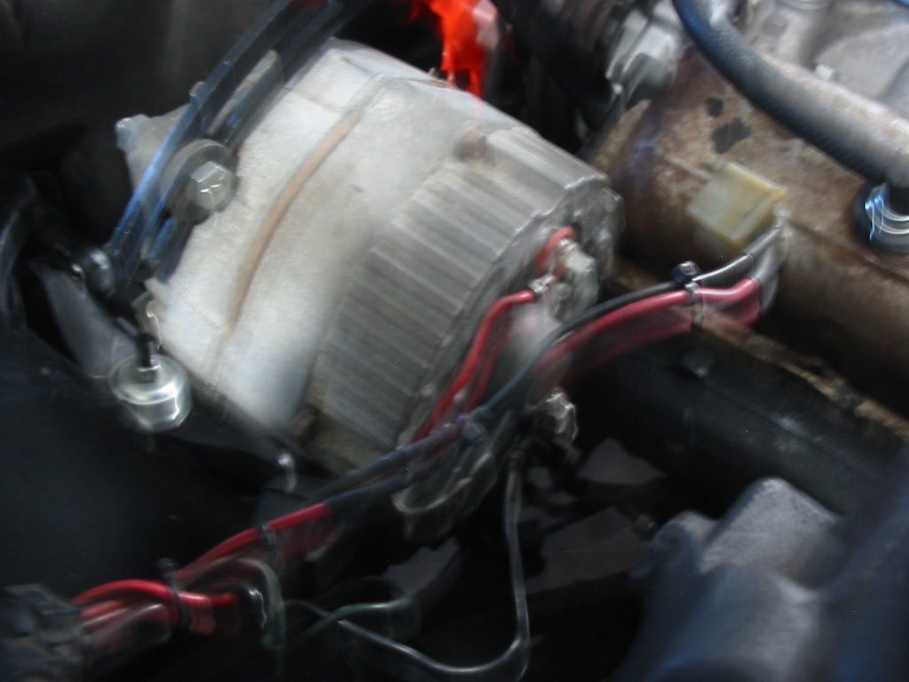
I’ve also put the alternator back and hooked up its wires.

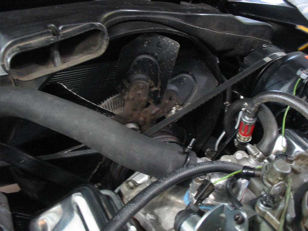
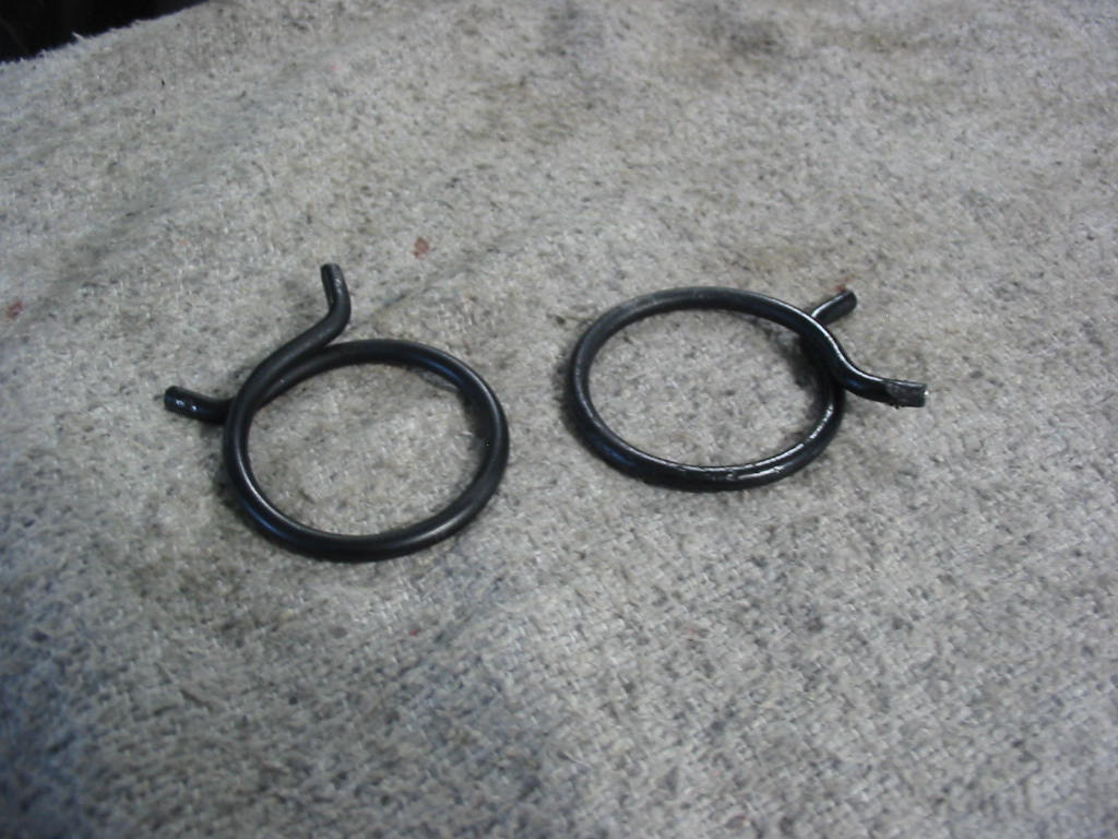
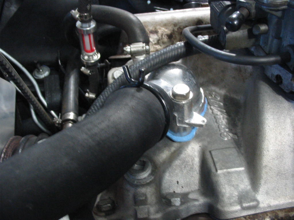
I’m also installing the upper rad hose. I like to use the factory wire clamps as they look a whole lot neater.

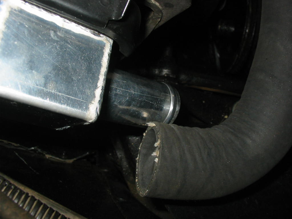
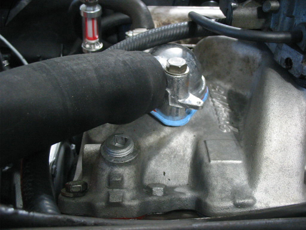
Foiled again! The upper rad water inlet is one size smaller than the replacement rad hose. So no option but to use a band clamp there. The replacement (China) thermostat housing has such a large ridge on the end that the wire clamp couldn’t be spread far enough with clamp pliers to get it over the end of the housing. I’ll try putting the clamp on the housing first and then push the new hose through the clamp.

I was able to do that so it looks more factory like. Unfortunately there are a number of band clamps on the fuel line.

Back to the exhaust.

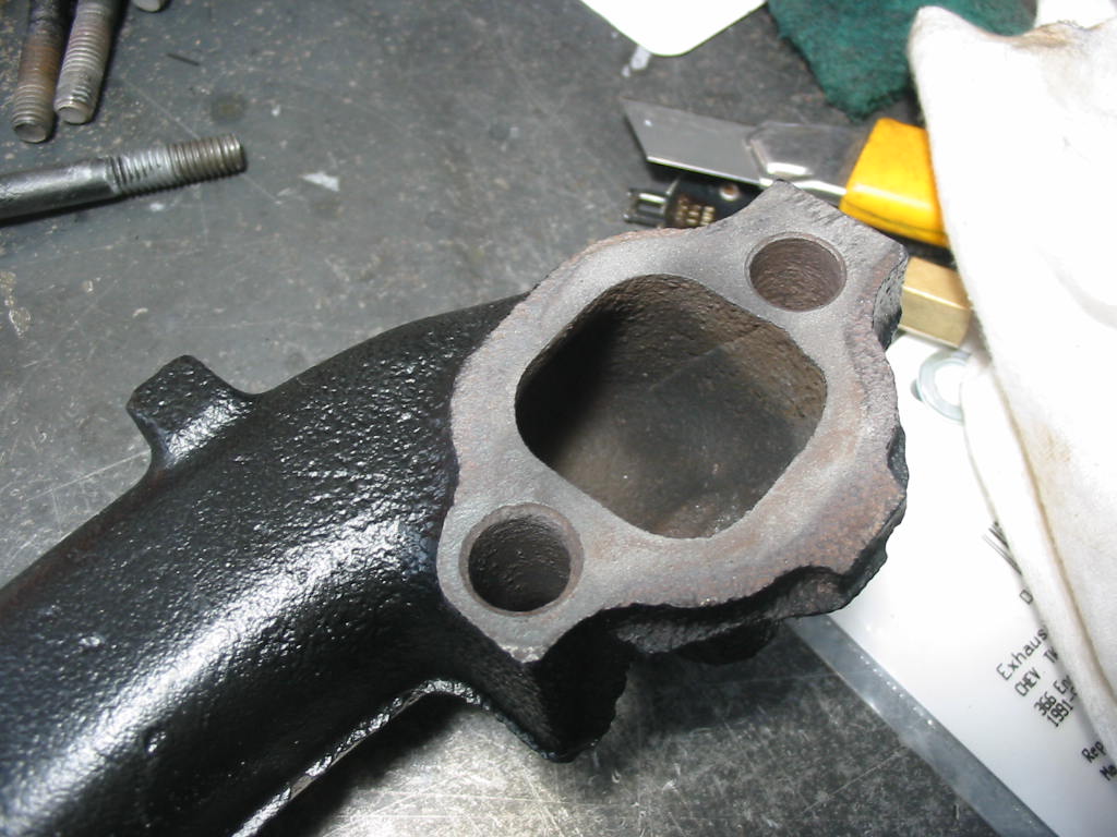
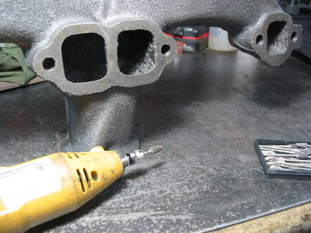
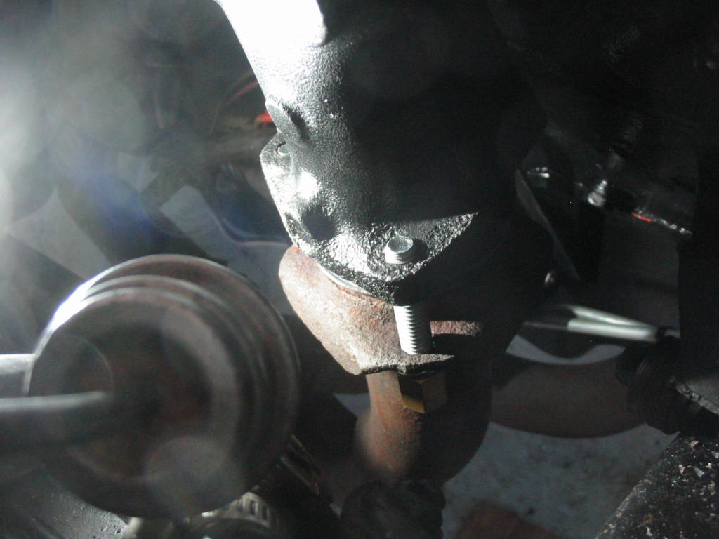
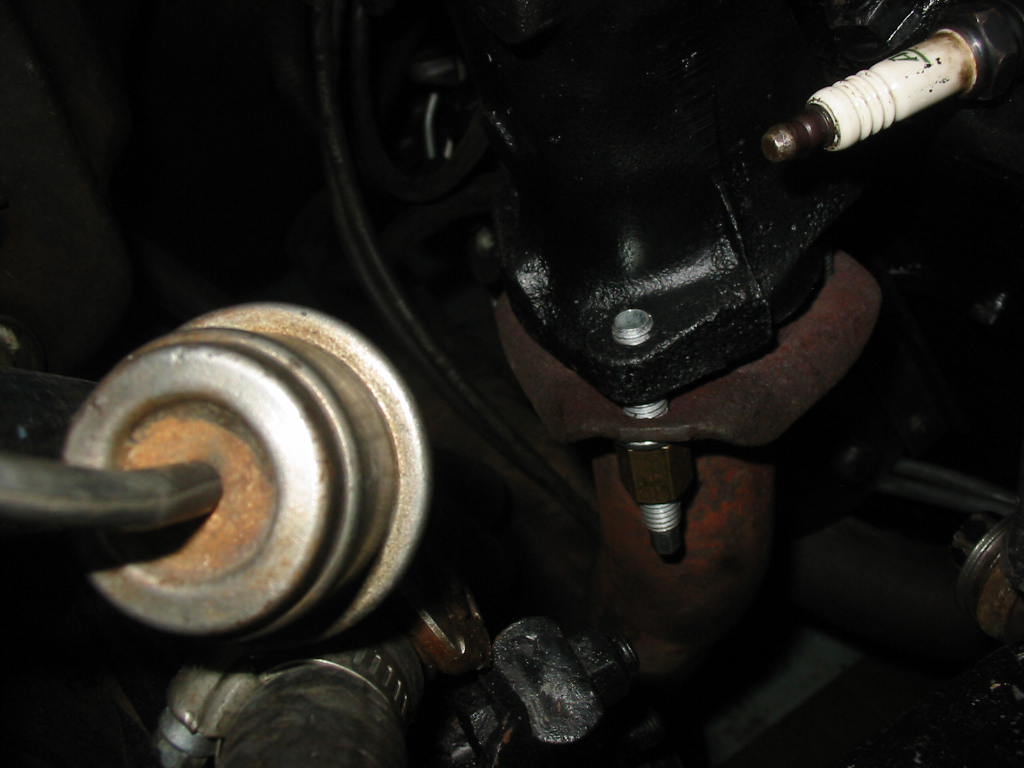
The upper shot is of the original factory exhaust manifold. The bottom one is the China replacement. As you can see the internal bore of the original is much smoother than the replacement. I didn’t go to the bother of grinding out the new manifold, but I will when I swap the original engine back in if I don’t go with headers or custom ram’s horn replacements.

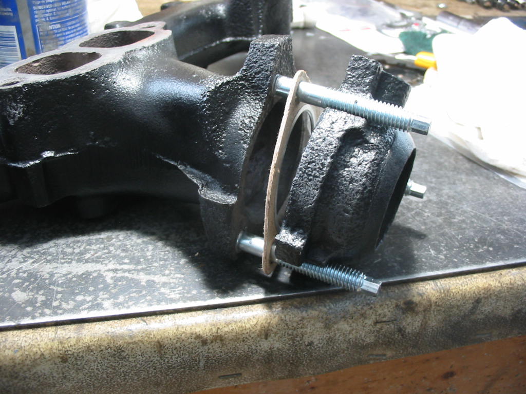
Time to install the new left side manifold. This is how the spacer will go back into the car. The spacer held the original flapper that channelled exhaust gases under the intake for cold start ups.

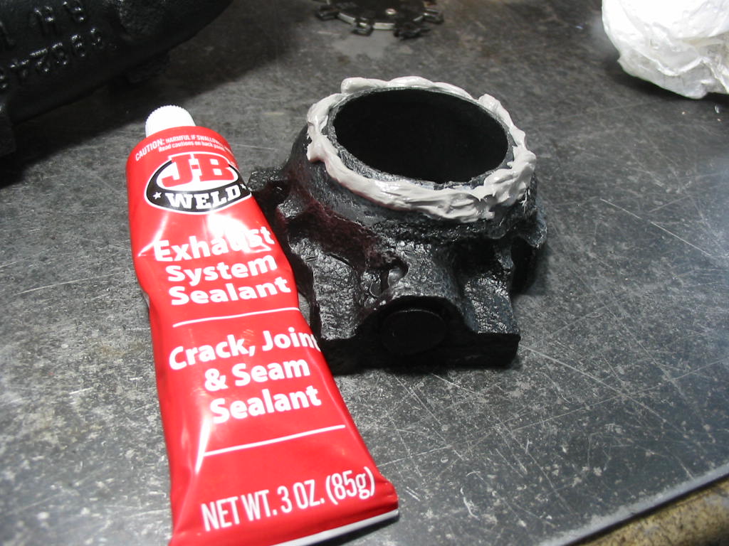
I’ve put a good bead of exhaust sealant on the side of the spacer that will fit into the exhaust pipe top. In the end there was no way I could fit the spacer in the system for some reason with the new exhaust manifold!

So I used a regular donut seal and it squeezed in place just nicely. Not sure what I would have had to do to get the original flapper/spacer in place if I needed the original intake heater to work.

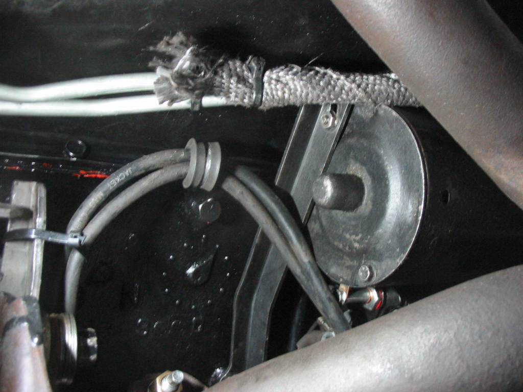
I was able to get the wire shield installed on the left side, but with the 305 starter and bracket in place it was impossible to get the shield on the right side. So I mounted a cushioned bracket to a pan bolt and ran the #2 &4 wires away from the exhaust system. I’ve also wrapped the transmission lines with header insulating wrap where they run near the exhaust pipe.

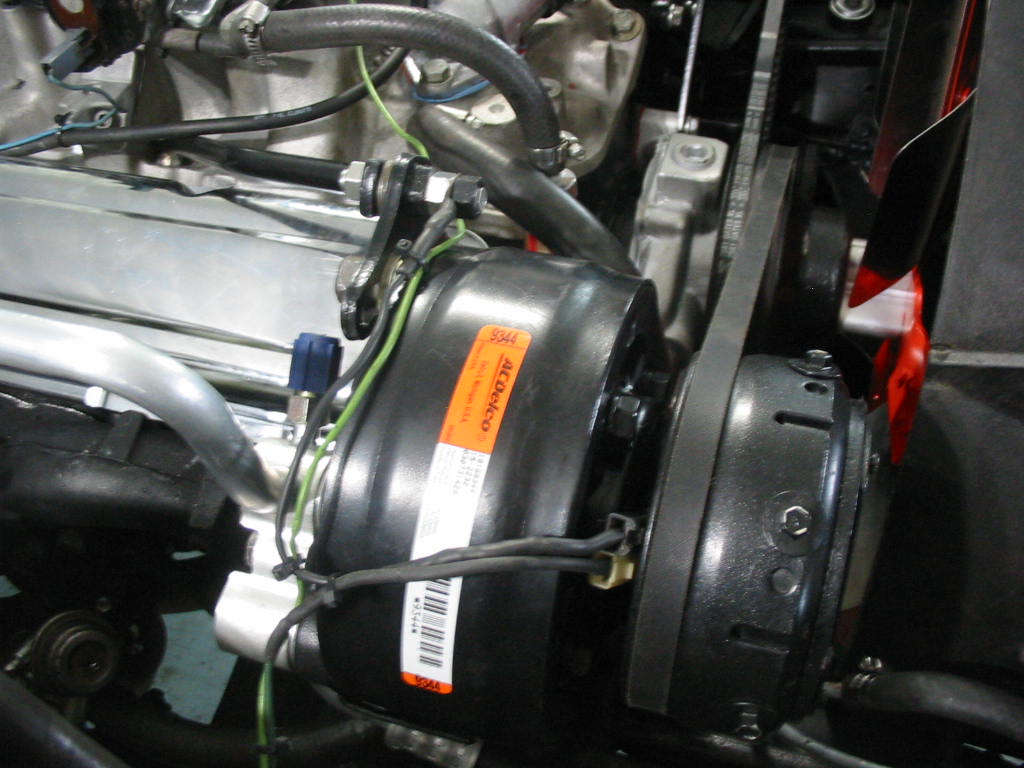
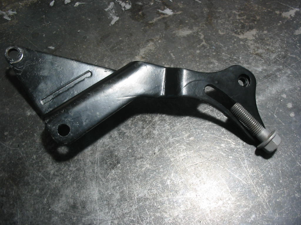
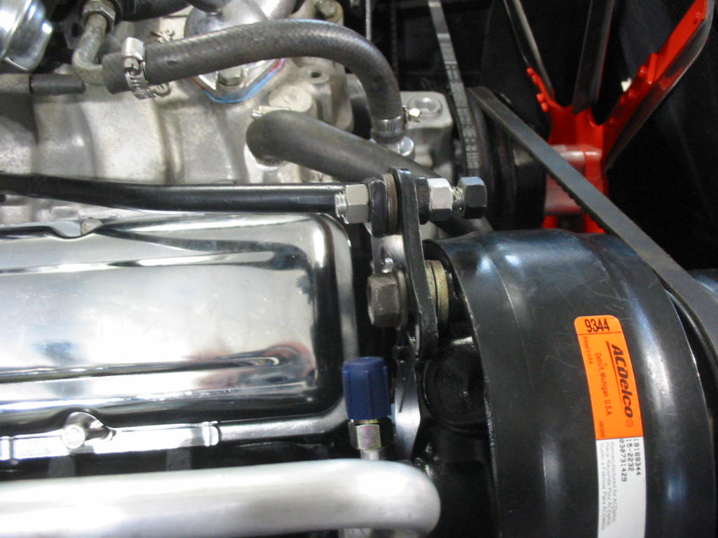
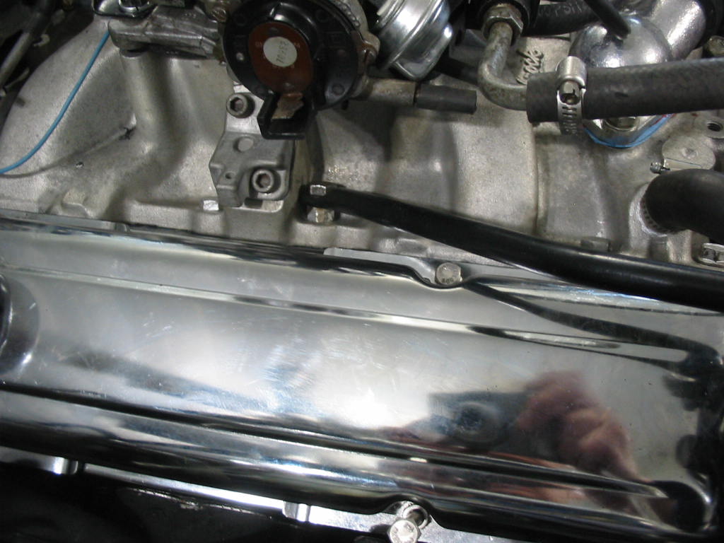
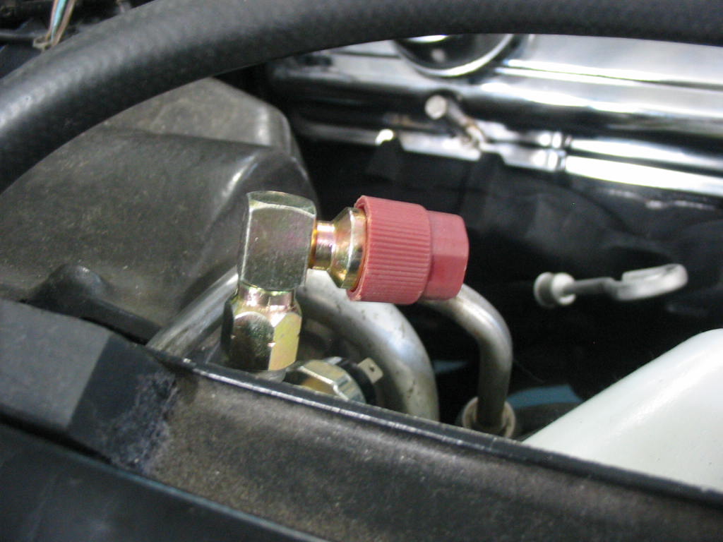
AC brackets in place.

Next: pretty well time to start the engine. Just need to add water and oil, put on the chrome valve covers and it will be time to get it going to check for problems and set the timing.

Back and forth

New rad nicely in place. Then I tried to fit the fan shroud….

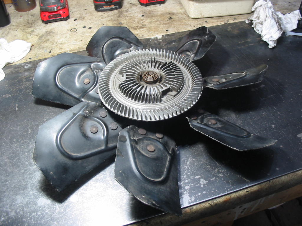
The rad had to come out again before I could get the shroud in place. It’s also the best time to install the fan pulley and fan. I’m going with a flex fan as they use less HP at speed and provide good air movement at idle. I’ve read you can gain 5 hp with them. That would cover the loss from the AC. I’ve yet to sand the fan pulley. I’ll use a short length of V belt and course sand paper to clear out the grooves.

Lots of bending and twisting to get the trans cooling lines close to where they need to be. I was supplied with a 90 degree and a straight fitting to make the radiator attachment. Turns out I needed to use a 90 degree fitting in both places. I also had to cut off a section of the output line. Here I’m using my double flare tool to make a bubble on the end of the line.

Works quite well if you just go a bit easy on the first step and don’t go all the way. The second 90 degree is visible on the right of the photo.

Both lines hooked up and ready to go:-) Not as neat as I would like and one reason I paid for custom lines! Not a happy camper about that.

Installing new studs in the exhaust manifolds. I have put never-seize compound on the threads just in case I need to remove them. I’ll also put the compound on the bottom threads as I will need to take the engine out in a year or so

.

The bottom gasket came with the new exhaust manifold. The top ones are Fel Pro and they are easier to put in place.

Next: getting the exhaust system in place.

A little ahead

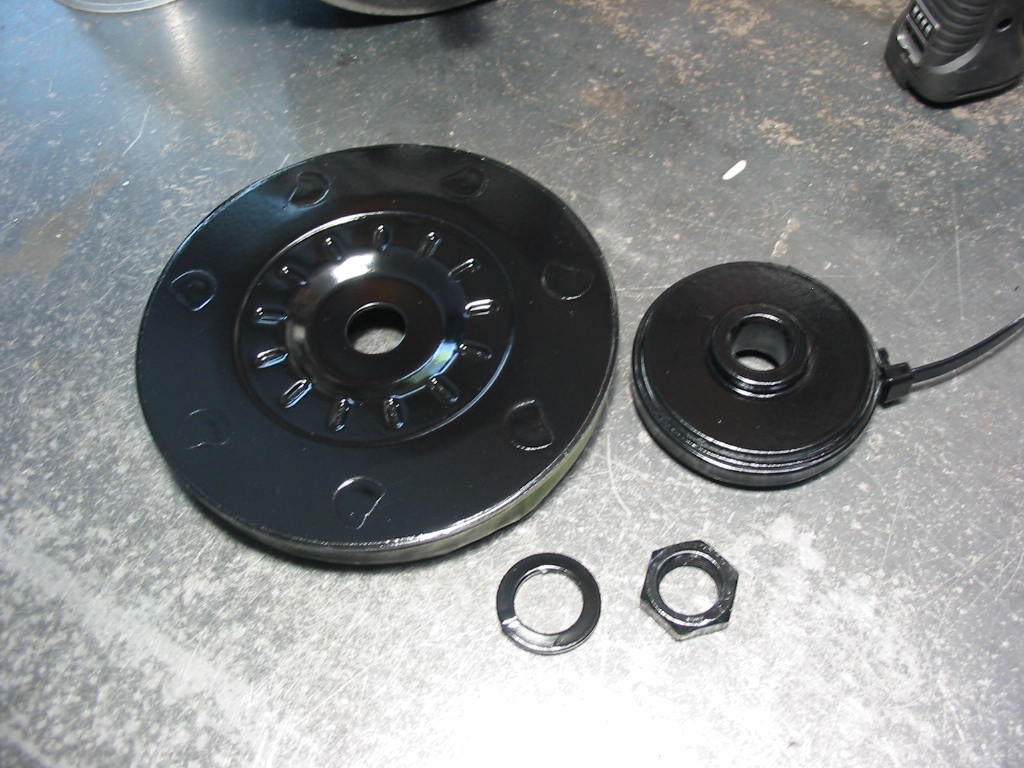
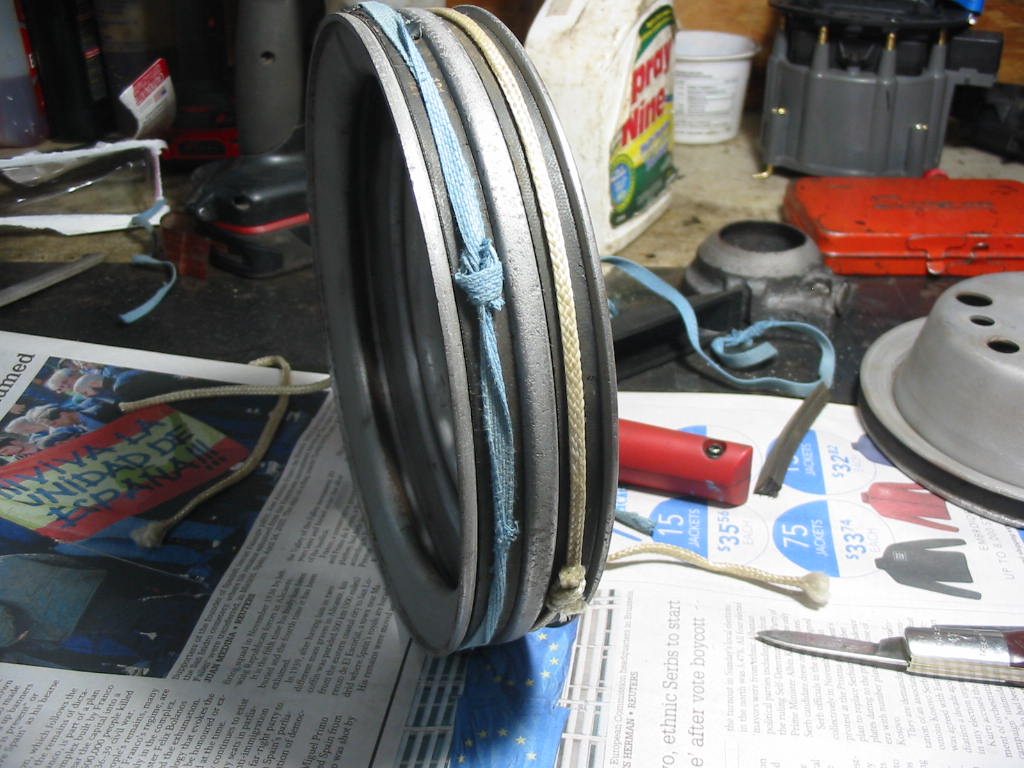
Getting the pulleys read for painting. I’ve cut lengths of V belt and held them in place with string. I painted the inside of the V slots in the pulleys before on a 360 Dodge engine. The belts tended to slip and squeal when reving the engine. It was hard sanding off the paint after.

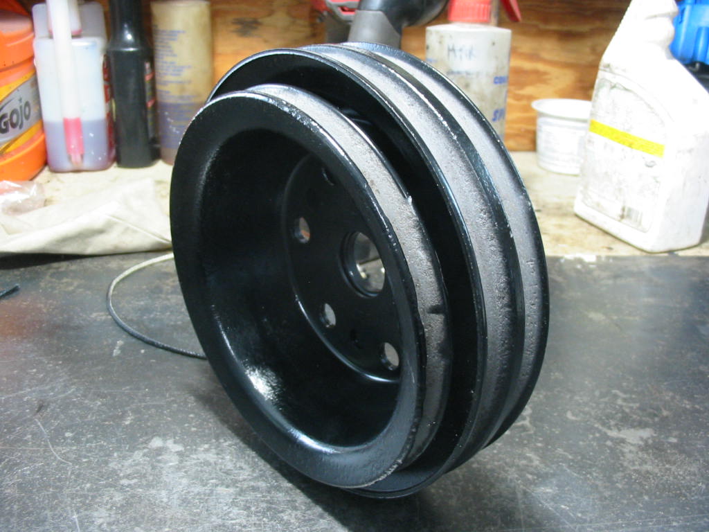
Pulley painted and clear metal where the belts ride.

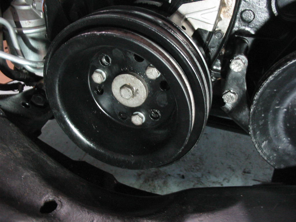
Pulley in place. The pulley bolts torqued OK without the engine rolling over, but I needed to put a blot in #1 cylinder so that when it reached TDC it was stopped by the bolt – I made sure that it was TDC on a compression stoke so that a valve didn’t get bent.

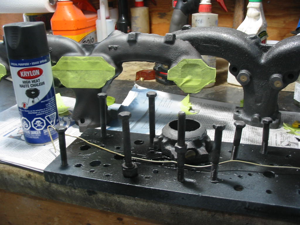
Exhaust manifold bolts and manifolds ready for paint. I’m using barbecue high heat paint. It’s good for sustained temperatures of 600 or so degrees and bursts as high as 1200 degrees. It doesn’t need to be heat cured so we’ll have to see how good it works.

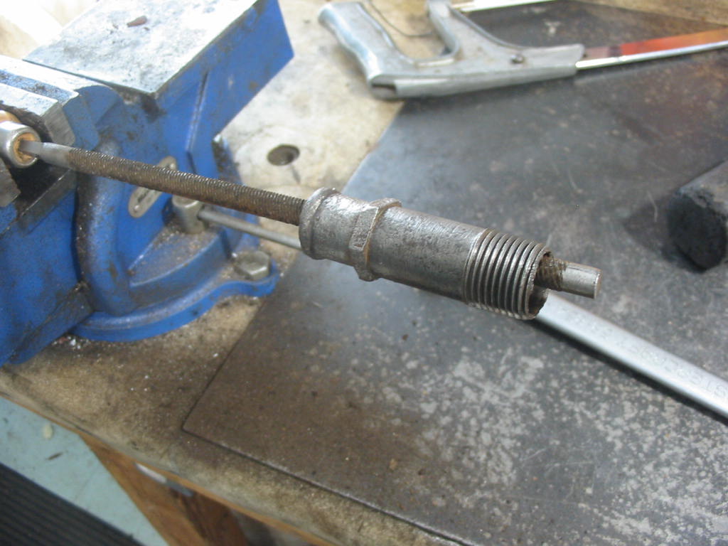
I’m using the old heater hose water pump connector. It was scaly on the inside . Rubbing it back and forth on a course rasp file did the trick to clean it out.

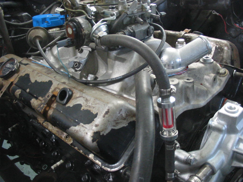
The connector can just be seen on the lower right. Here I’ve installed the clear fuel filter and hooked it all up to the carb. I had to do this before I could re-connect the fuel lines to the fuel pump other wise fuel might just pass through the pump and onto the floor.

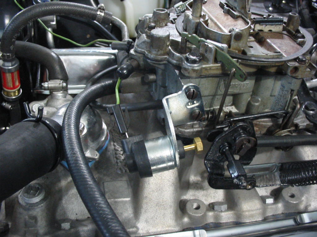
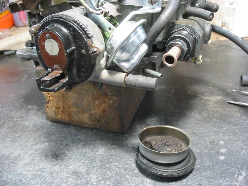
I’ve installed the electric choke that was on the 305 donor engine. I like them better than the original temperature units. Seem to work faster and more consistent. Fortunately it works on an earlier Quadrajet.

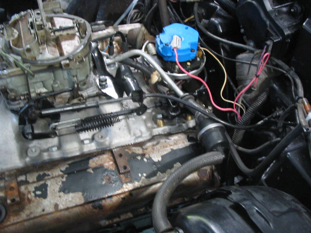
Getting the throttle hooked up plus the vacuum lines.

Next: one step ahead and then one back!

Working underside

Installing the two transmission cooler lines. The lines come pre-bent, but I didn’t find that they fit all that well. I had to do a lot of bending to get them in place. It is a bit of a nightmare to get them connected to the trans. I used fingers, a bent wrench and a 1/2″ crow’s foot to get them on and tightened. It’s the only crow’s foot I have and it was absolutely necessary to get the fittings tight.

The original Chevy motor has a special clip welded to the pan that holds the trans lines. There was none on the 305 So I used a couple of cable ties and a generic bracket to keep them steady.

The pipes are generally in the right location, but there will still need to be some bending to get them placed right.

I attempted to fit the new starter from the original Chevy engine (left) only to find out it wouldn’t fit. The old starter from the 305 donor works but the solenoid got damaged when it was removed.

Fortunately the solenoid from the newer starter fitted the old 305 starter. Instead of two long bolts the 305 starter takes a short and long bolt (left). The newer starter bolts are also a bit longer.

Starter in place with two mounting bolts. All it needs now is the support bracket from the back of the starter to the block. A tight fit, but just enough room to slip it in between the block, exhaust pipe and trans lines.

Next job was to connect the shift cable to the trans. The original rubber cover was rotted out. I couldn’t find a vendor that sells new ones. I would need to buy a whole new cable setup to get the rubber! So instead I used a length of bicycle inner tube. I put the shift in park which moved the cable to it’s full length and then cut a length of tubing that was a bit longer and fastened it on with cable ties.Seems to work OK and it will keep road grit out of the cable housing. Note the photo is looking up at the bottom of the trans.

The new left manifold has arrived from Rock Auto. It has steel plugs in the air induction openings. The manifold finish is not as smooth as the original, but it doesn’t have as many bumps in the casting so looks nicer that way.

I’m replacing the steel plugs with brass ones. I’ve added a bit of exhaust system sealant to ensure a good seal. The brass will be easier to cut off than the steel.

Final job before sandblasting and paint is de-burring the exhaust ports and other bits left off from the manufacturing process.

Next: on towards getting the engine started

Moving ahead

Bits and pieces ready for the rad frame to be installed.

Rad frame back in. It’s a bit of a tight fit and I’ll be painting over some scrapes on the fender aprons! Other wise ready to install the AC condenser and the new radiator.

A new ‘fail safe’ 195 degree thermostat. A bit of red sealant to make sure there are no leaks from flaws in the metal.

Not the original outlet, but rather a new unit used on older engines without the modern emissions fittings. A neater look and I have disconnected the EGR and the cold weather warm-up systems (the under manifold heater and the warm air induction system from the manifold to the carb via the air cleaner). I’ve snugged up the bolts by hand and will torque to spec in a day or so.

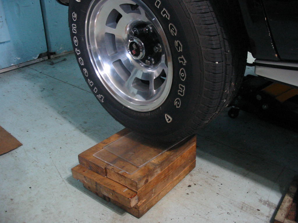
The alignment shop (OK Tire) could only set the toe on the front end. The caster was OK, but the camber was out. They wouldn’t attempt to change the shims to get it in line. The alignment tech did note what it would take to get the right front tire aligned.

Even though the tech wrote ‘add shims’ shims actually need to be removed to adjust the A arm outward to move the camber from negative to positive.

Fortunately there were four 1/8″ shims that could be removed. Two from the front and two from the rear.

There are still some shims at both ends. I torqued down the bolts to spec and all should be OK. I will still need to do an alignment as I have changed all the bushings in the rear suspension. It will likely now be out of spec. Another $100 to the alignment shop!

Movin’ along, the AC condenser is in place.

Next: I will be putting the power steering pump and front crank pulleys in place before fitting the new rad. In the meantime I’ll go underneath and bolt the flex plate to the torque converter and get the trans cooling lines in place.

More prep work

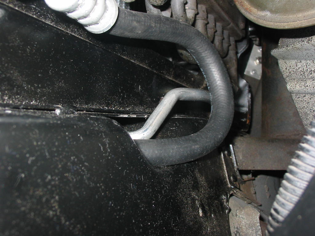
I won’t be doing much to the AC condenser. I am straightening the flattened fins. Likely won’t make a big difference, but … A piece of thin plastic works fine.

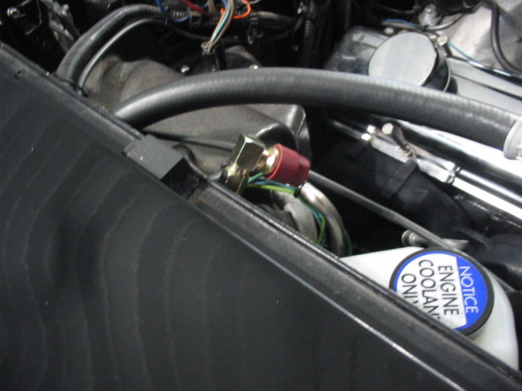
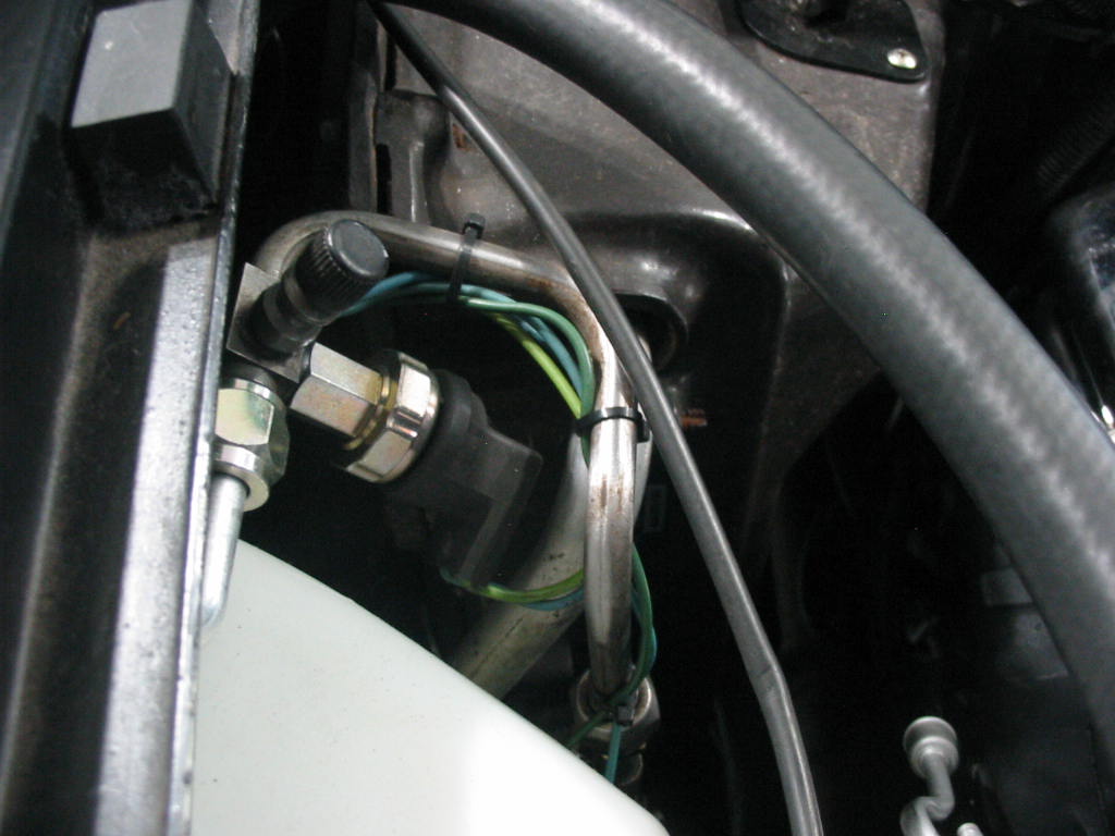
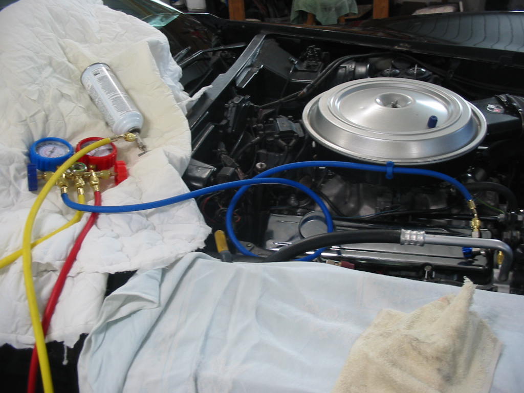
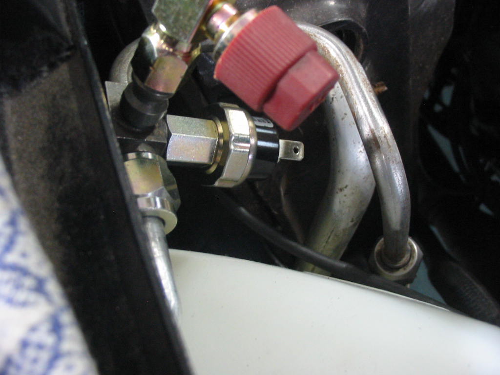
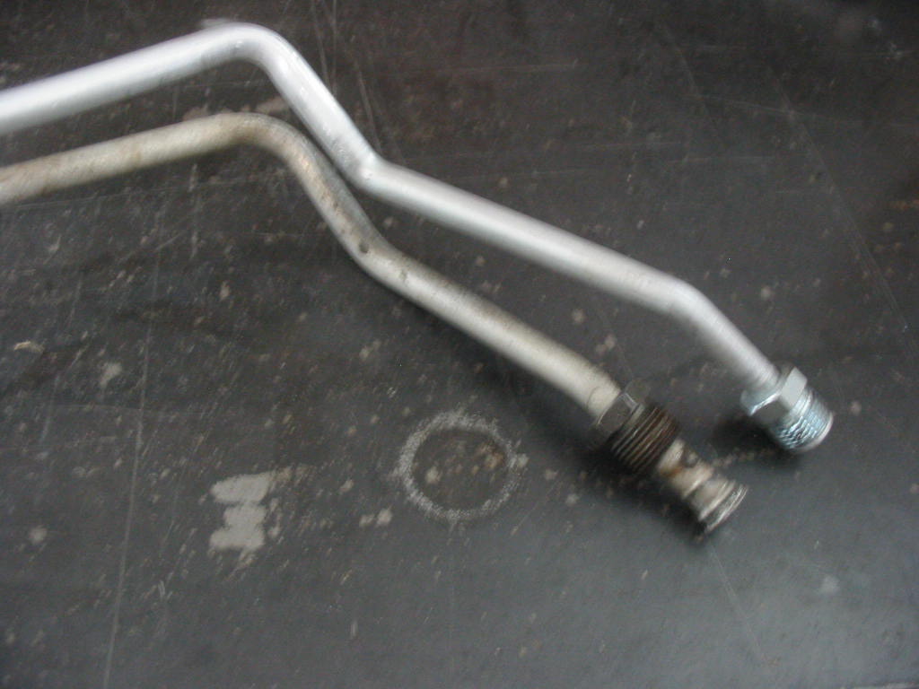
Working on the short connector high pressure pipe. It holds the AC low pressure cutoff switch and the high pressure port. The kit I got contains fittings to convert from the original R12 system to 134A. I will likely use R22 gas when the time comes to charge the system.

I had put lots of penetrating oil on the bolts over a few weeks and with my impact wrench they all came out of heads OK. It seems by the casting numbers that they are both right hand manifolds so I guess they must be very similar. That’s the good news.

The bad news is that one of the ears is cracked on the manifold that came off the right side. Now to find a used one or a new one – no used ones locally that are up for sale so ordered a left side unit from Rock Auto for $120 at my door tax in.

I’ve blocked off the heat riser passages in the intake so I don’t need the flapper in the right exhaust pipe. I still need the unit as a spacer so I removed the flapper and tapped the bushing for a standard bolt.

I didn’t tap the bushing all the way in so that the bolt would jam tight. I also uses lots of blue lock tight and then cut off the bolt head.

This side of the flapper body fits into the exhaust pipe. There is no provision for a donut gasket??? So I’ll pick up some muffler cement and use that to seal between the unit and the exhaust pipe.

The high rise manifold has a casting bump that stops the TV cable bracket from mounting properly. So I cut a couple of brass bushings from a piece of brass pipe and used them along with longer intake bolts to get the bracket in place. It is actually better because the carb is higher with the new intake and the TV cable will be lined up better.

Since the heat riser passages in the intake are blocked I also need to block the opening for the choke heater tube as it can’t fit with the passages blocked. This is an Edelbrock block off plate. I will be using an electric choke on the Quadrajet in the final setup.

Next: On to the rad frame and installation of the AC condenser and the new aluminum rad.

More prep work.

The engine is now in the car, but there is still work to be done to connect everything back up. Here I’m working on the rad/AC condenser frame. It and all it’s associated screws and clips need to be cleaned, sanded, cleaned again and then painted.

Hung up to paint in the garage upper floor – my default painting room:-) It’s in flat black here and will need a final coat of semi-gloss. The nice thing about all this work is that I won’t need to do it again when I re-install the original motor/trans.

The original rad cushions were toast after so many years. I decided to try and make my own.

I used some closed cell foam to make new cushions. They are a tad thinner, but I hope they will work and I can put the $70-$90 cost of a new set to other uses.

I tried to install the driveshaft only to realize I forgot that I had to install the yoke first and then slip the driveshaft in. A tight fit. I had earlier coated the universal strap holder bolts with blue locktight. They were stiff to screw out which is good.

Driveshaft in place with the yoke re-attached and the back of the driveshaft to the differential flange.

The clip on the left is the factory style clip to hold the parking brake cable to the frame bracket. It may work OK if the bracket is perfect, but mine have been damaged over the years and the clip isn’t holding securely. I ordered some C clips from Amazon. They have a 12.5 mm opening and 8mm arms.

They fit nicely over the parking brake cable holding it to the bracket. One side was tight, but the other was a bit floppy so I squeezed the arms in a bit and it fit OK. I would have preferred to have an opening of 11-12 mm, but I couldn’t find any.

Next: more reassembly prep work.

New air dam & 305 install

New plastic air dam in the original style. My old air dam was split in the centre and a couple of the mounting points were damaged.

A mounting screw was broken off in the support bracket so I decided to remove the brackets and give them a going over.

Engine lined up for the install. Just need to put the trans and engine mounts on and then I can attempt to get the unit in the Chevy.

I had lots of clearance and with the rad support out and shortened chains on the hoist.

The adjust able hoist worked well getting the engine/trans down and under the trans hump.

Had issues getting the long arms of the hoist under the car moving back. I used a 2×4 to coax them them back and then a 2×6 to bang the arms back when the arms were well under the body – a bit primitive, but it worked.

Of course the jack stand got in the way! I put a hoist under the frame a bit further back and removed the stand. I only needed another 5″.

Once I got the hoist arms back enough the engine could be slipped in place. The engine got itself jammed with the trans tail shaft to one side. It would have been nice to have someone underneath guiding the tail shaft into position. I only had to pull it out a bit, align the tail shaft and then it moved back enough to be dropped onto the front engine frame mounts.

Next: time to hook things up starting with the underside components.

AC dryer install and onward

The new dryer is a multi-fit unit and has a selection of three tubes for attaching to the bottom. This one seems closest to the original, but in the end I used a different one. The mounting bracket is loosely fitted here.

At this point in the install of the AC I’ll be attaching low pressure line to the dryer. I needed to find a couple of plugs to close off the pump connection. I need to keep the dryer as free from moisture as possible and it will be only after the engine is installed that I can finish the AC install.

The new dryer has two ports where the old one only had one. The second port gets in the way of the mounting bracket so I had do do a bit of a mod to the bracket to get it to fit.

Dryer in place. I have used a short ‘U’ shaped tube on the bottom and ran the hose from there. The original setup had the hose wrapping around the back of the dryer.

New splash shields in place with new push rivets – lookin’ a whole lot better.

Next: a new air dam and checking the rear wheel rotor run-out.

More boring engine bay prep

Some new parts in: recovery tanks, bleeder screw and AC orifice tube. Strangely I bought the parts from Northern Corvette, but for some reason the parts came from Rock Auto??? I ordered a new orifice tube as I wasn’t sure of the old one and it was the only component that could cause problems and require the system to be opened – not good for the new dryer if that had to be done.

Drivers side clean up before paint. The A arm splash shield has been removed. It was toast. I have new ones on order.

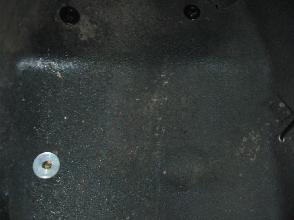
One staple holding a small splash shield on the lower front side of the apron pulled through the rubber. I used a thick 3/16″ aluminum pop rivet and washer to fix it back in place.

Time to start the job of scratching and scraping away years of collected crud.

I got at least a pound of accumulated dirt and grease off the frame.

Cleaned with a small wire brush, a tooth brush and parts solvent. Then a go over with paint thinner.

Looking a whole lot better with a coat of Tremclad semi-gloss rust paint.

Next: getting the AC dryer in place and on to the engine install – hooray!