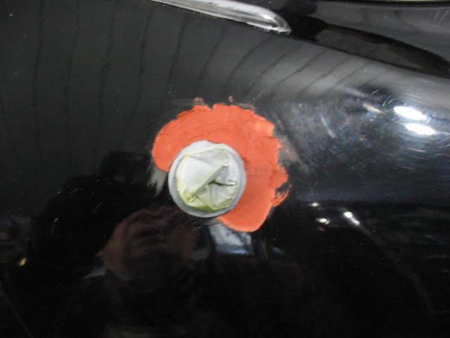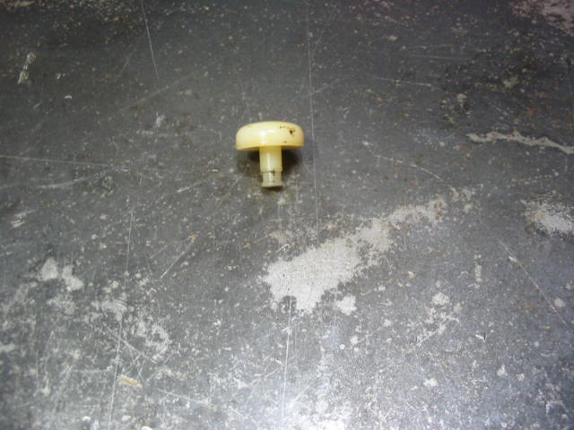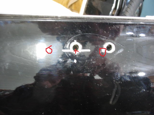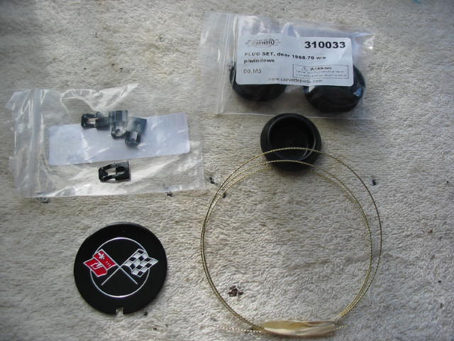
A small order in from Corvette Depot. A decal to cover the carb heater access hole, some specialty clips used in the door linkages – I don’t need them right now, but good to have on hand to save waiting if one gives out, some door access plugs and a length of cutting wire for windshield removal.
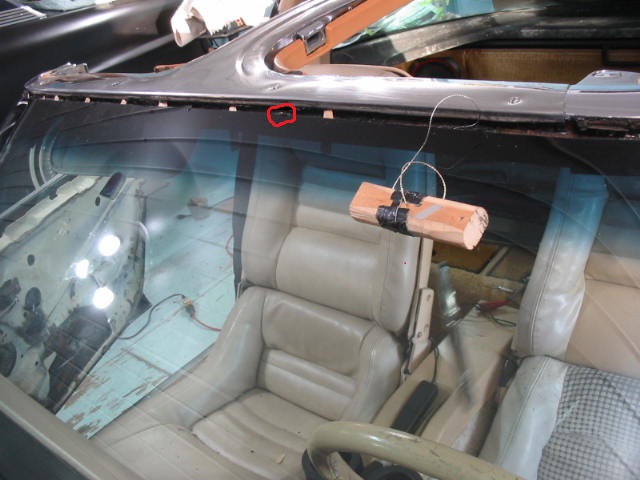
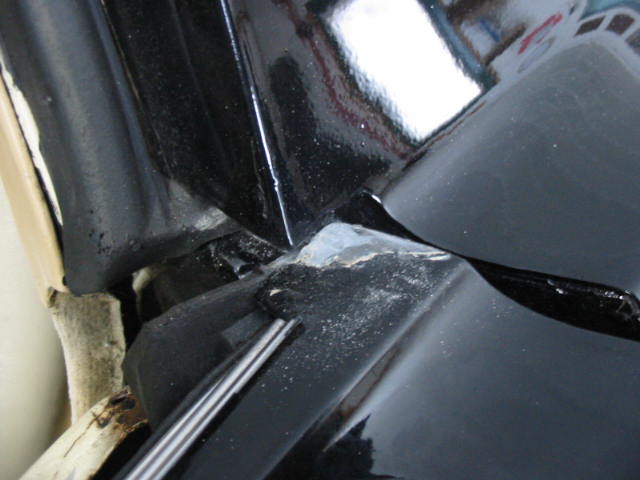
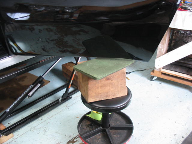
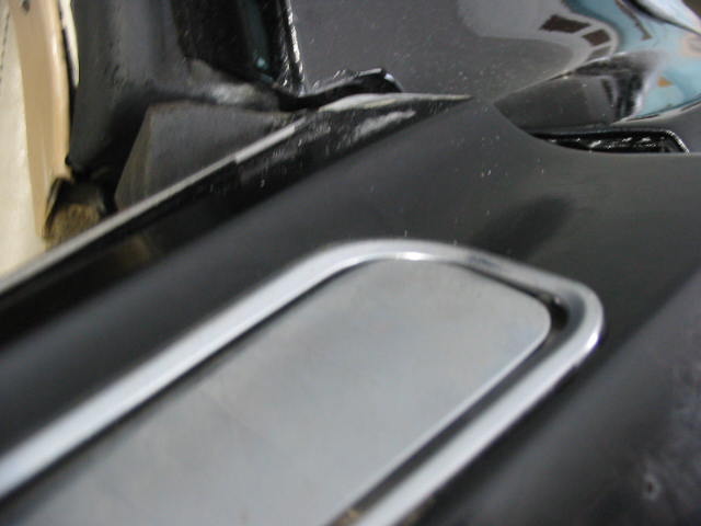
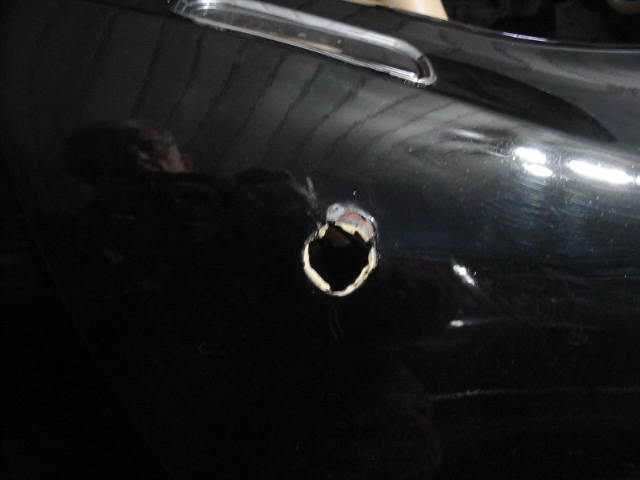
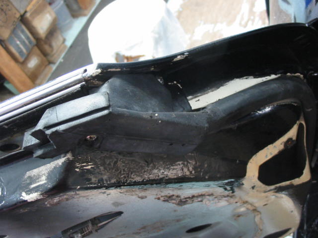
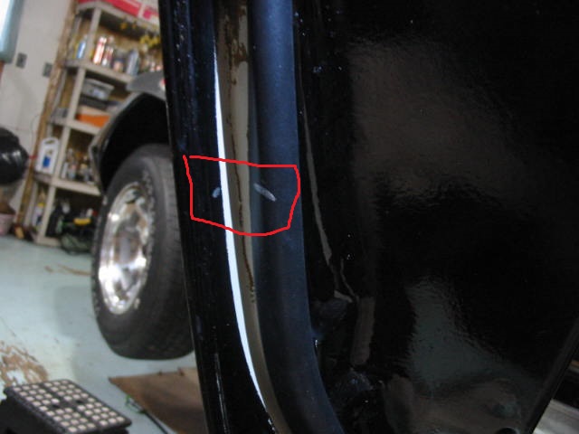
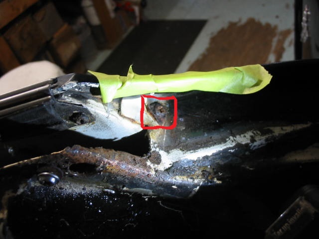
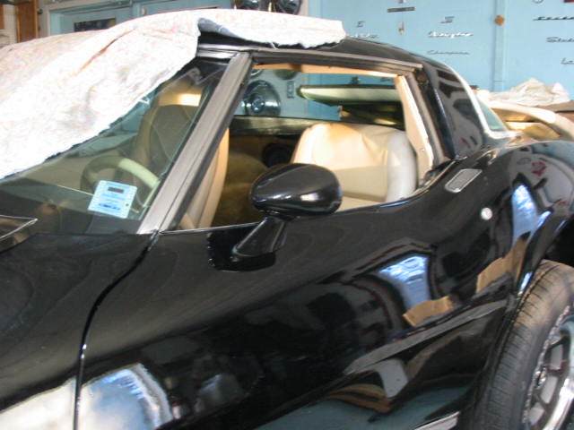
I’ve made my way up the passenger side of the window and along the top. I have been using a utility knife to cut the bead on the ouyside and on the inside along the edge of the window frame. I’ve been pushing in small wooden wedges as I go along to help keep the seal from re-attaching itself. I don’t know if I caused the chip or the chip was already there, but it is a cause of concern (red circle). I will stop the freeing of the windshield until I get the drivers door finished – I need to have the drivers side door-to-windshield upright in place to fit the door window.
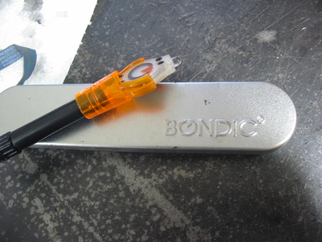
This is an epoxy bonding kit I picked up from Princess Auto some time ago. Very handy for fixing cracked plastic, etc. The left side of the device holds the epoxy and the right side is a UV light to harden the epoxy. I’ve put a dab on the chip and hopefully it will stop and cracking.
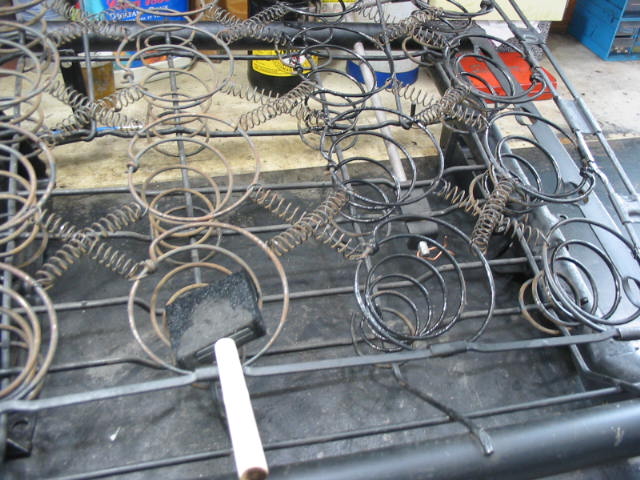
I have found a way to easily paint the seat springs. A foam brush works very well so I did all the springs on the bucket seats for the Studebaker.
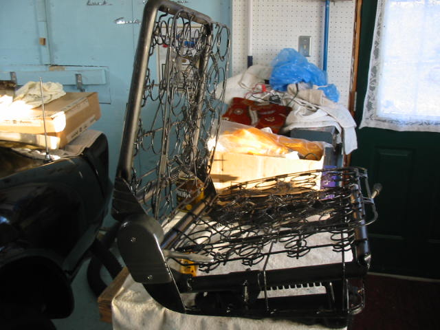
All painted and assembled with the reclining mechanism in place. Now to get the upholstery shop and see if and when I can get them done.
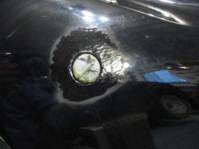
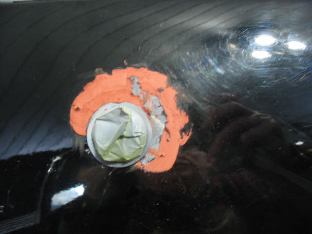
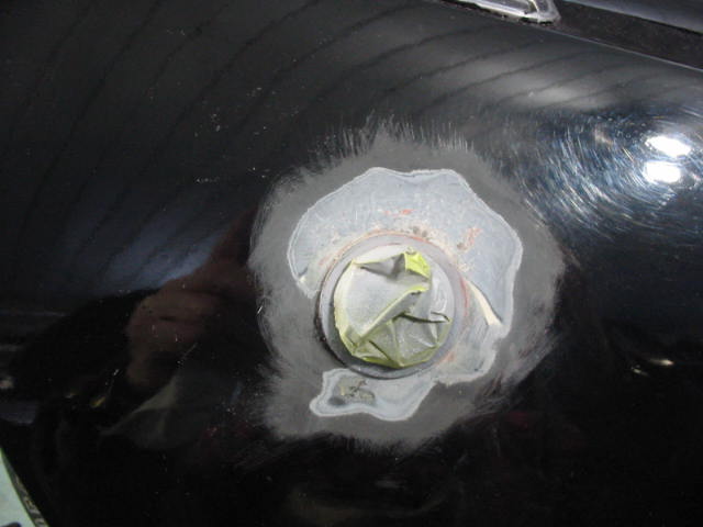
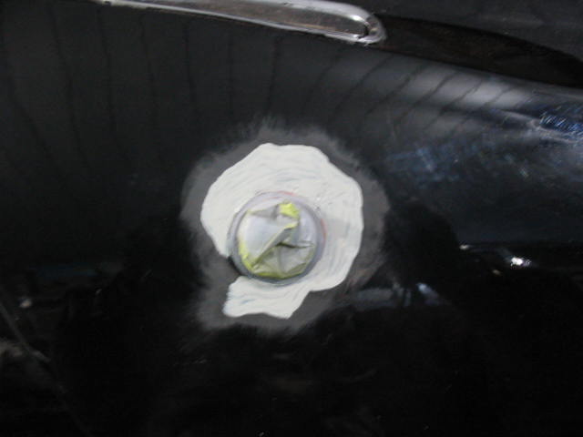
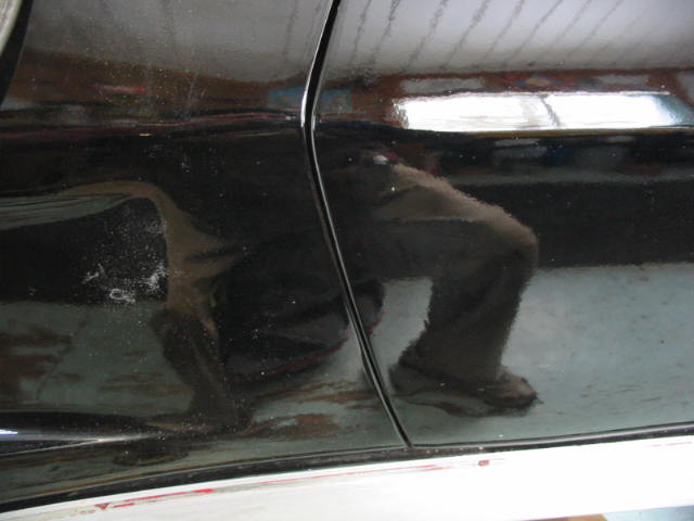
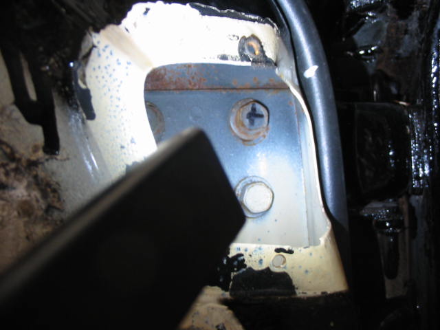
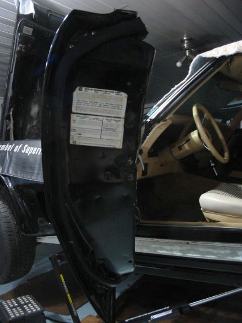
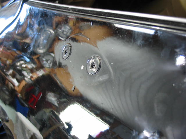
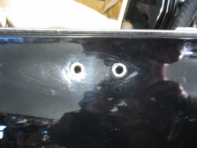
Back to the door repair. I put on a couple of coats of Tremclad gloss black and after two days I wet sanded it until it was smooth. Now I will add another couple of coats of paint and hopefully after a couple of days I can wet sand and polish.
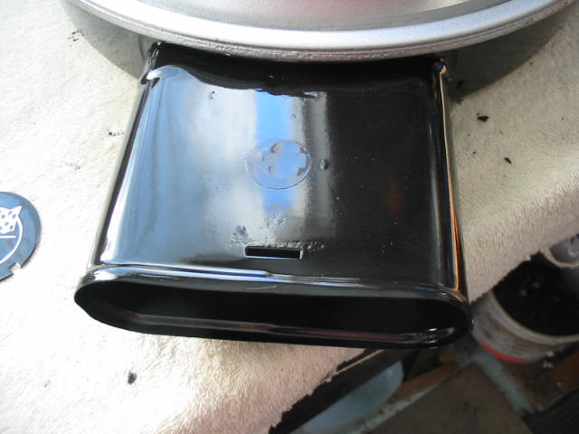
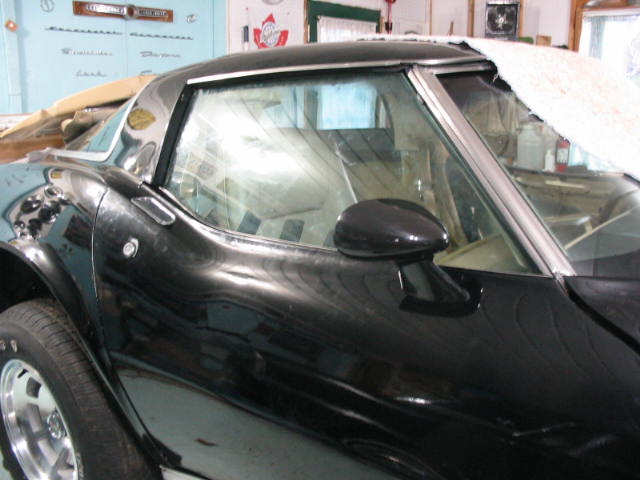
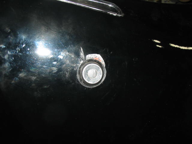
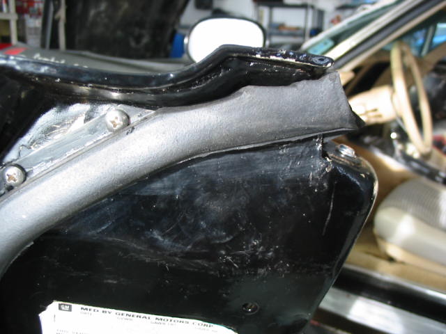
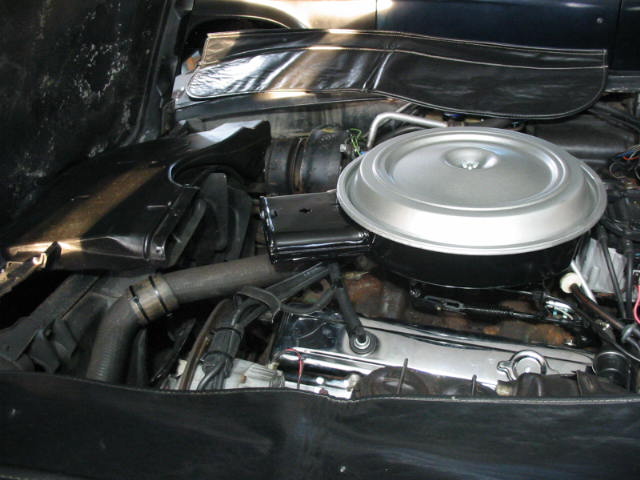
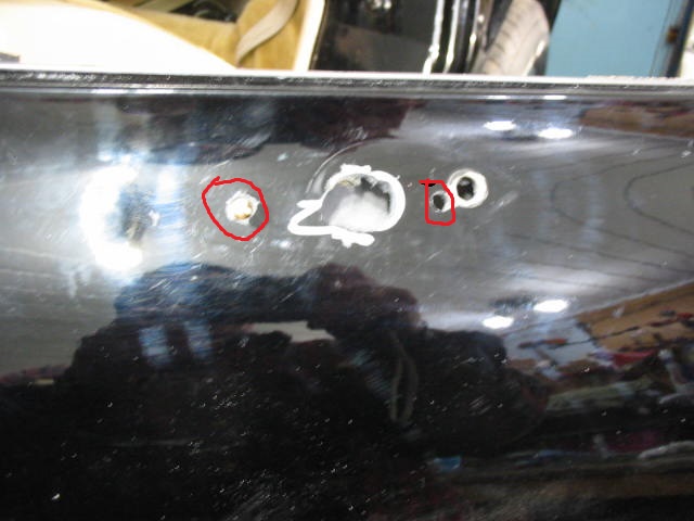
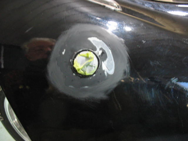
I have already covered the hole in the snorkel with black pinstripe tape.
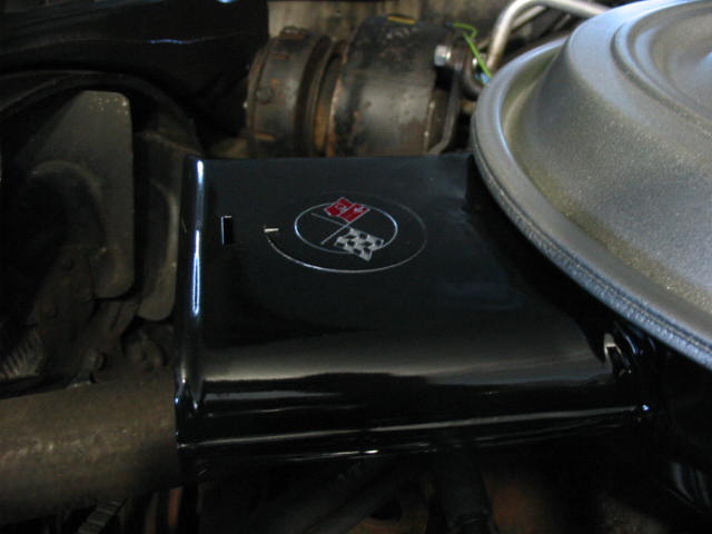
Looks much nicer with a Chevy decal over the hole.
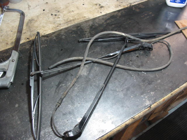
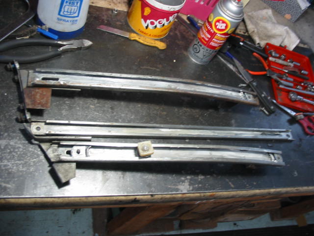
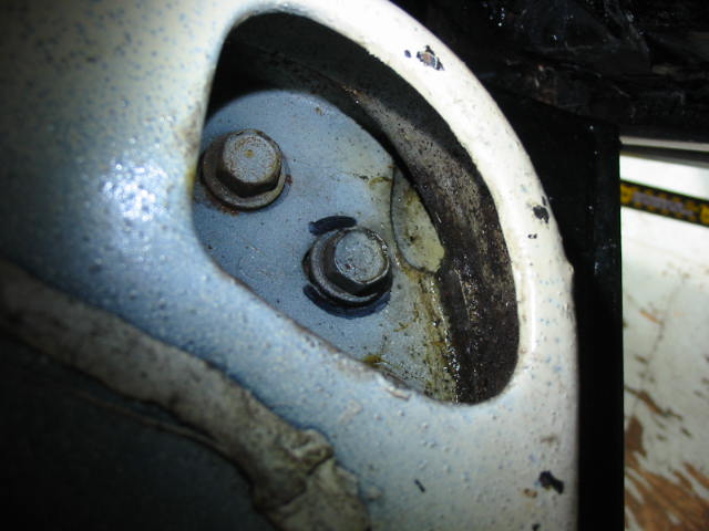
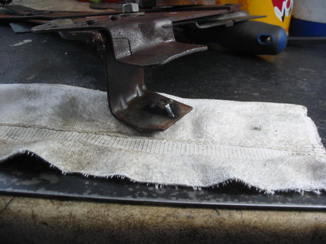
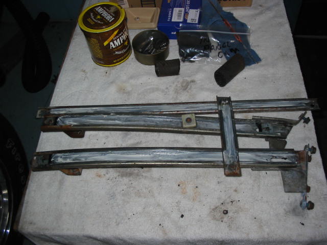
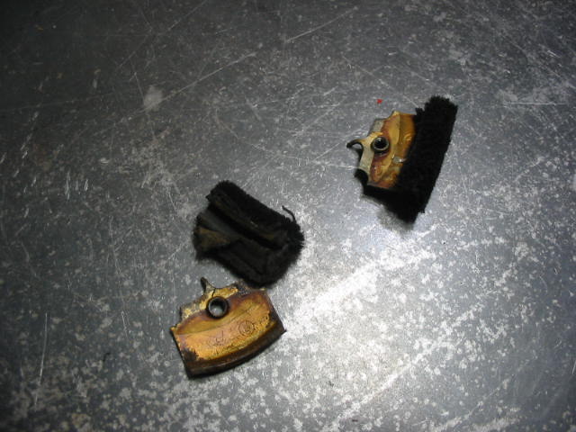
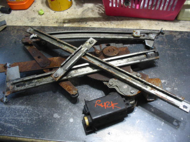
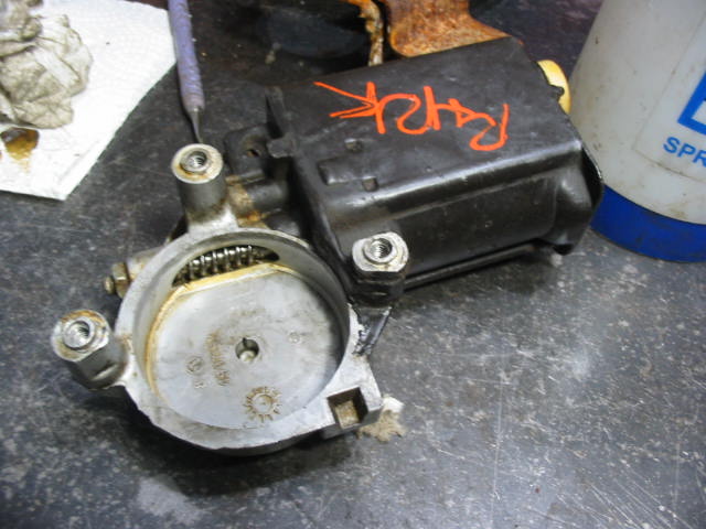
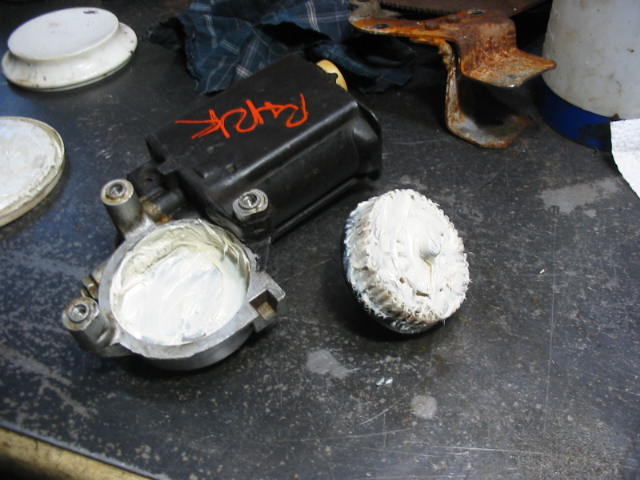
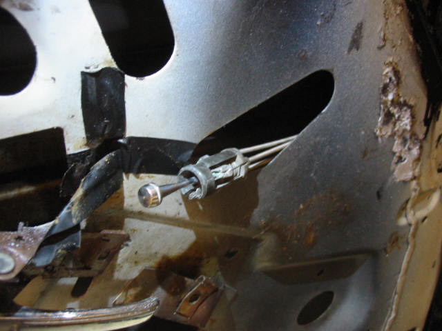
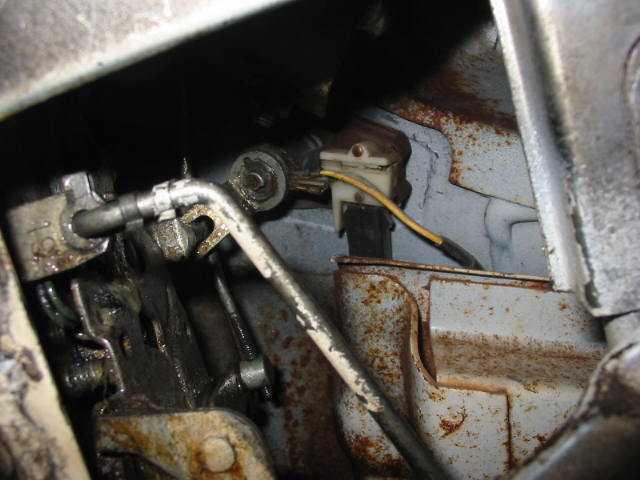
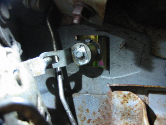
I need to remove the wipers to complete the windshield work so a good time to give them a bit of an overhaul.
Next: hoping for parts to arrive from Zip Corvette.