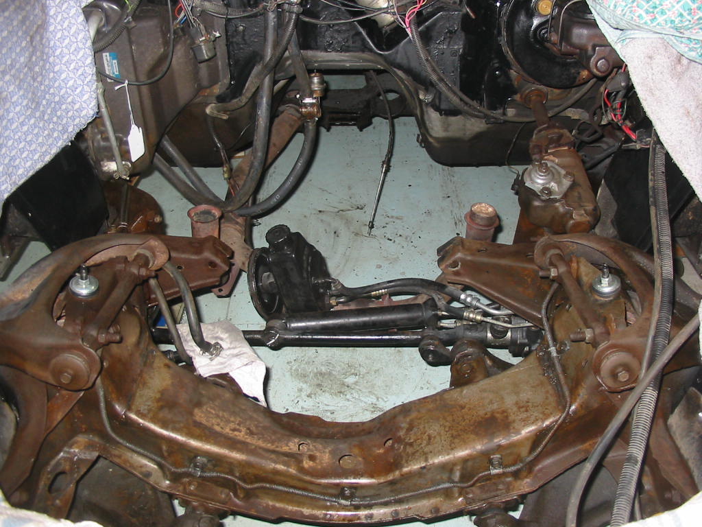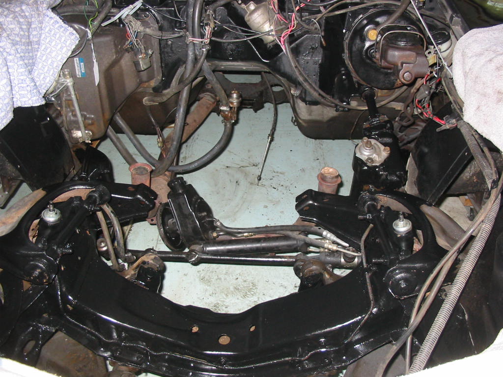
AC and engine bay prep

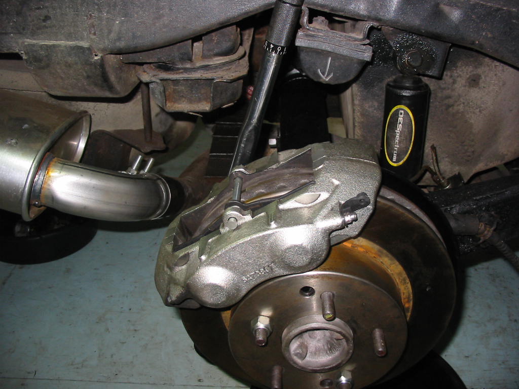
Calipers back on. A bit of a grunt to get the bolts torqued using the inch lb wrench as the longer Ft Lb tool won’t fit. The ‘bride’ helped me to bleed all four calipers working from the longest line to the shortest. I wasn’t happy with the amount of air coming from the rear calipers so I redid them and sure enough I got lots of air out to the left rear unit.

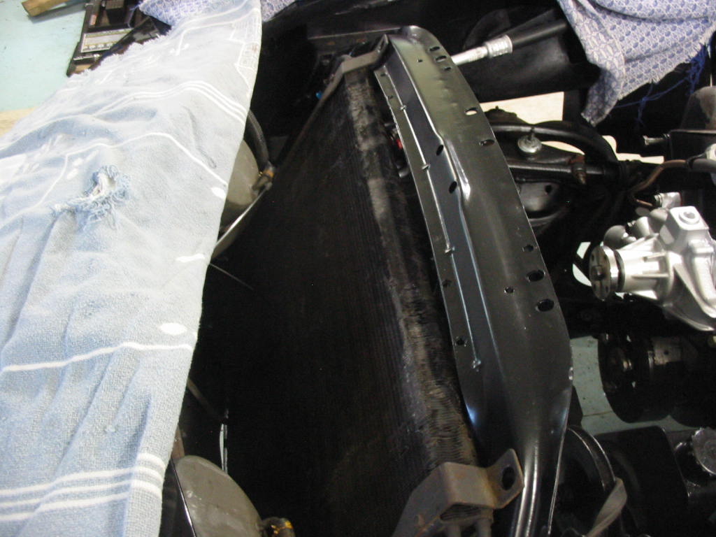
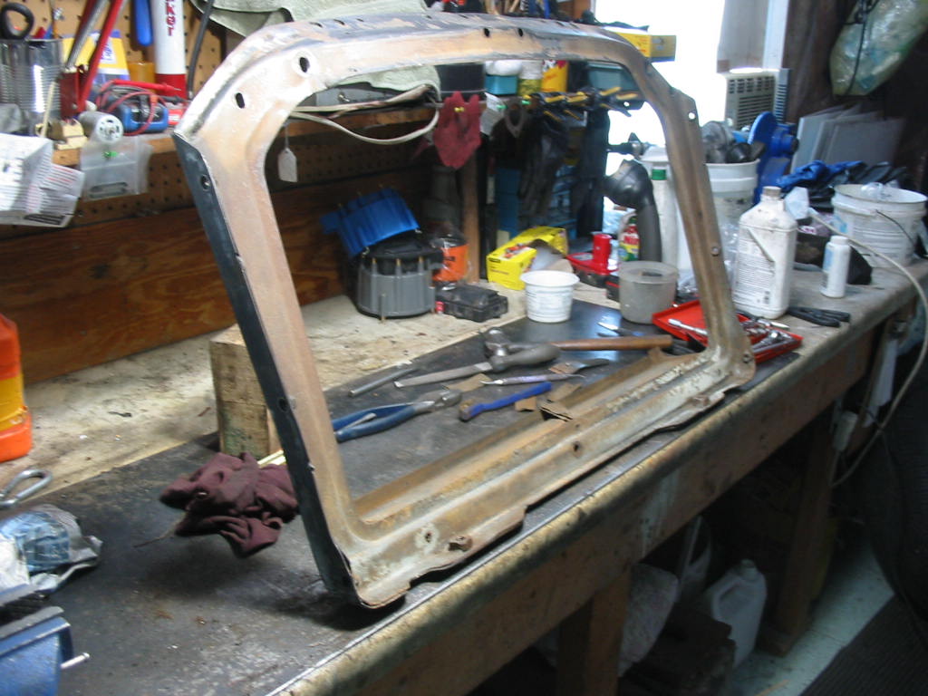
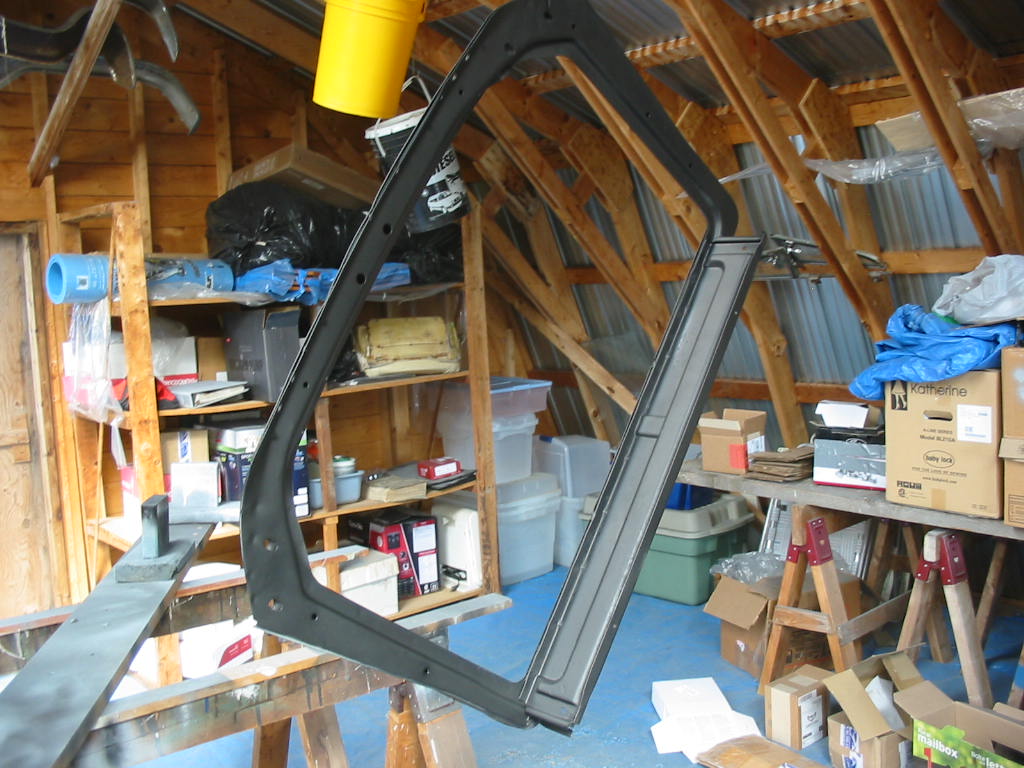
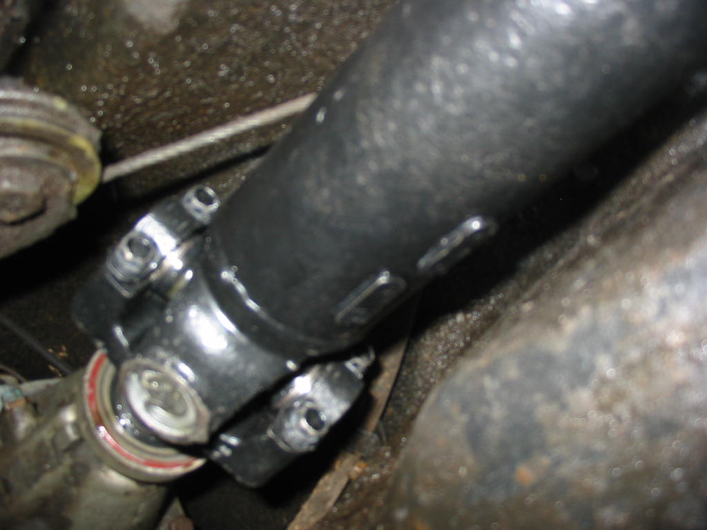
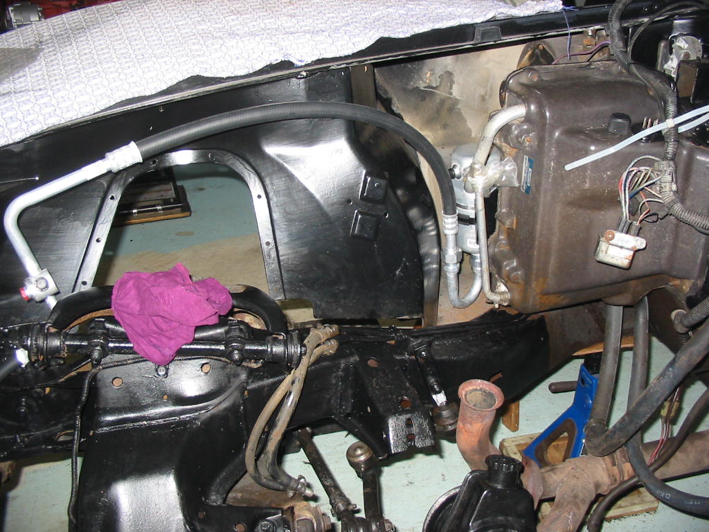
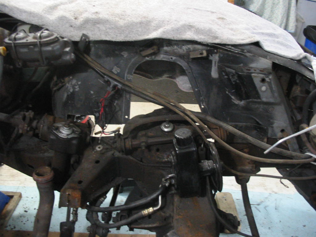
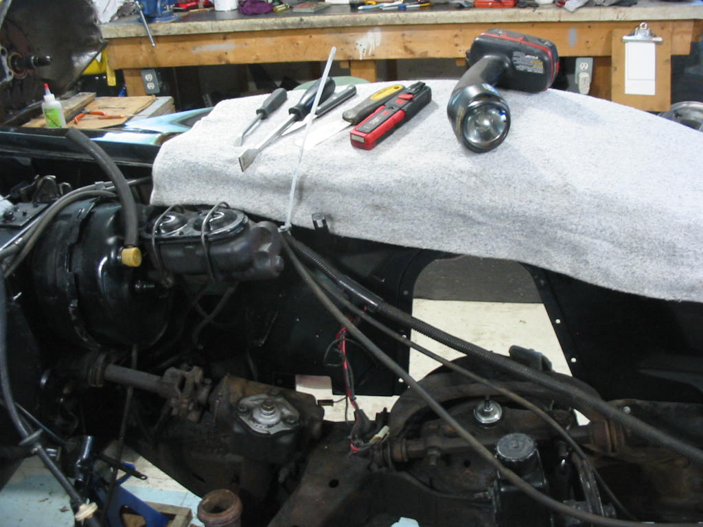
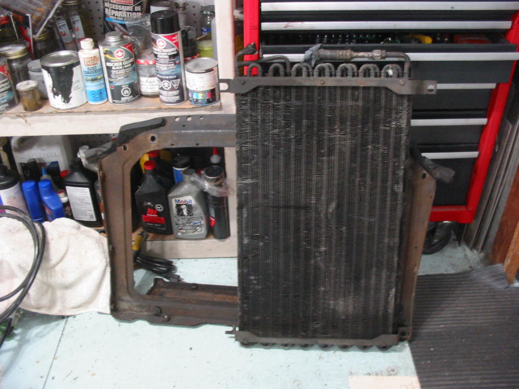
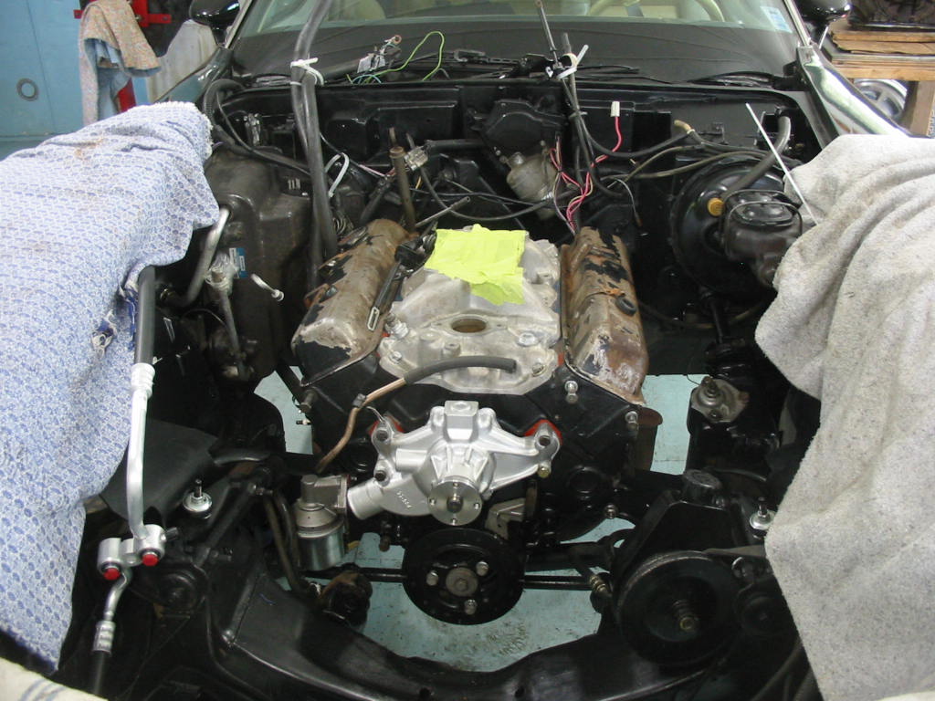
I’ve removed the AC condenser and the rad frame. My ceiling isn’t so high at about 8′ so I want as much room as I possible to get the engine/trans unit into the car. This will also make it easier to clean and paint the rad frame and the front of the engine bay.

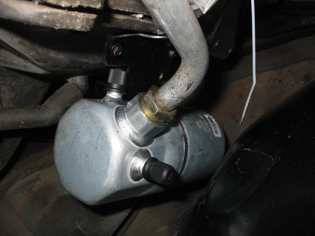
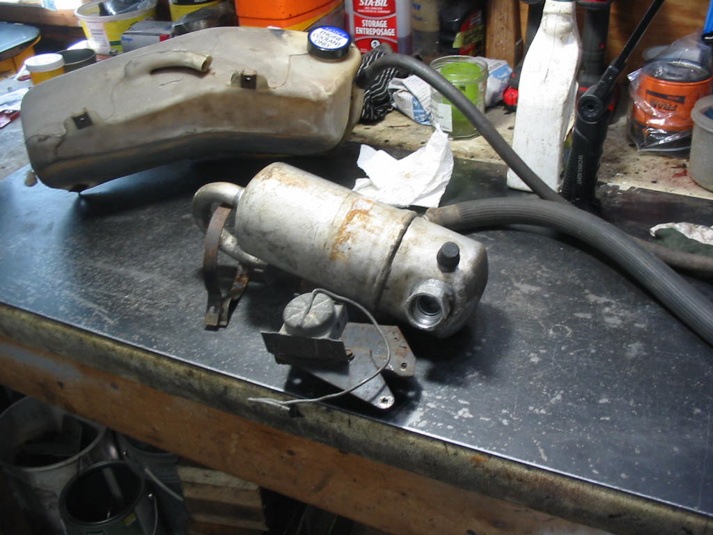
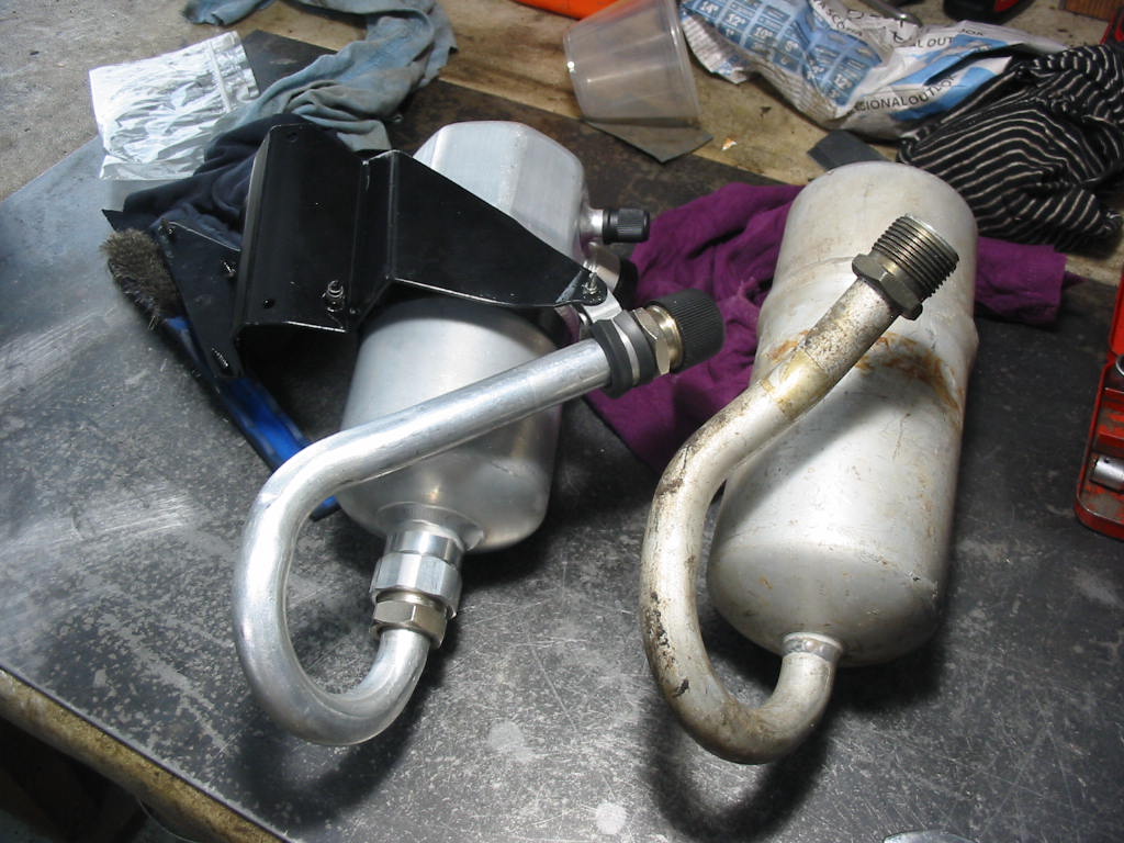
AC dryer, frame and thermostatic switch. A beggar to get out even with the recovery tank removed.

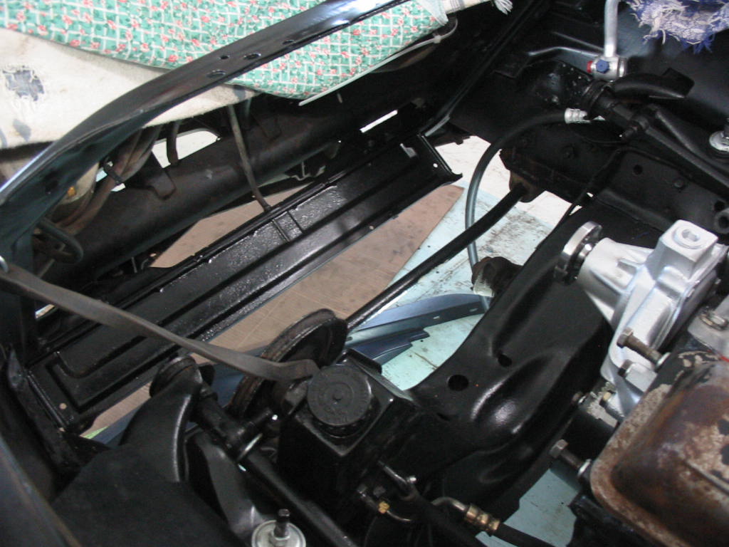
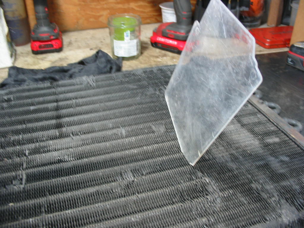
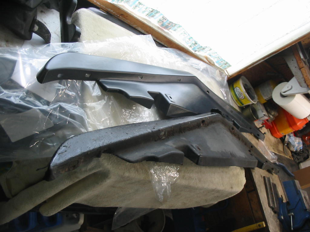
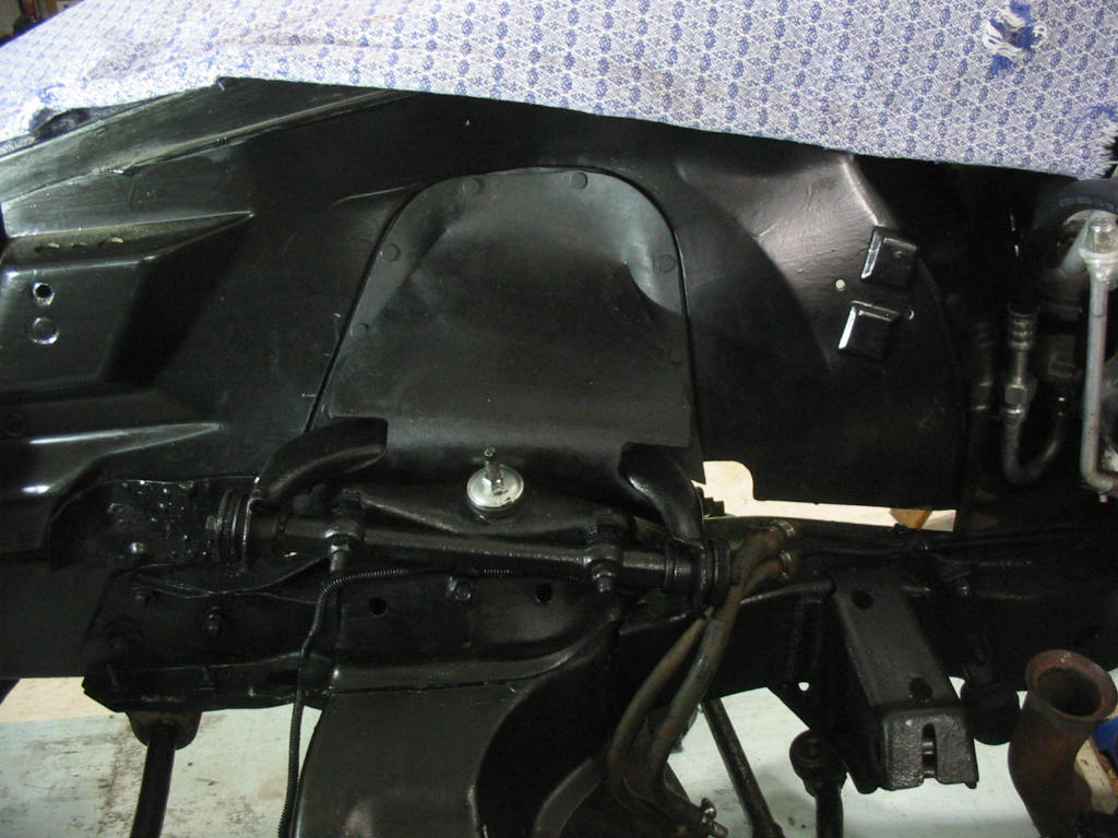
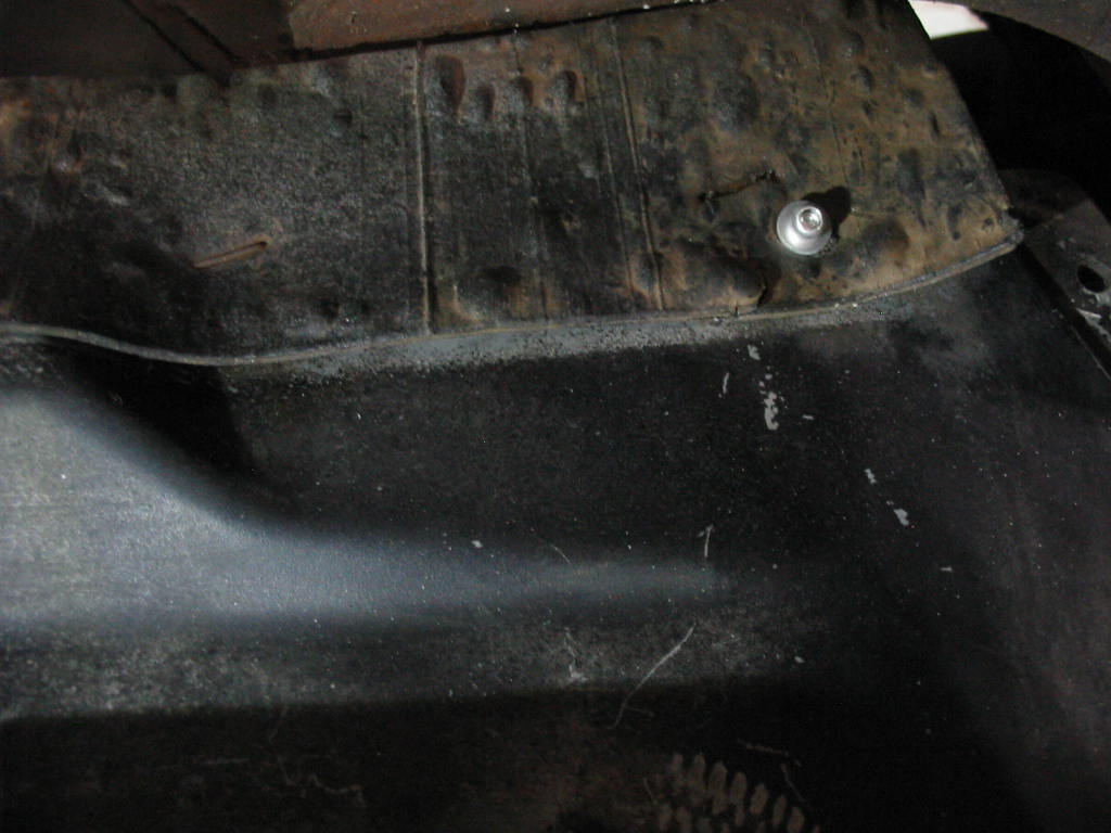
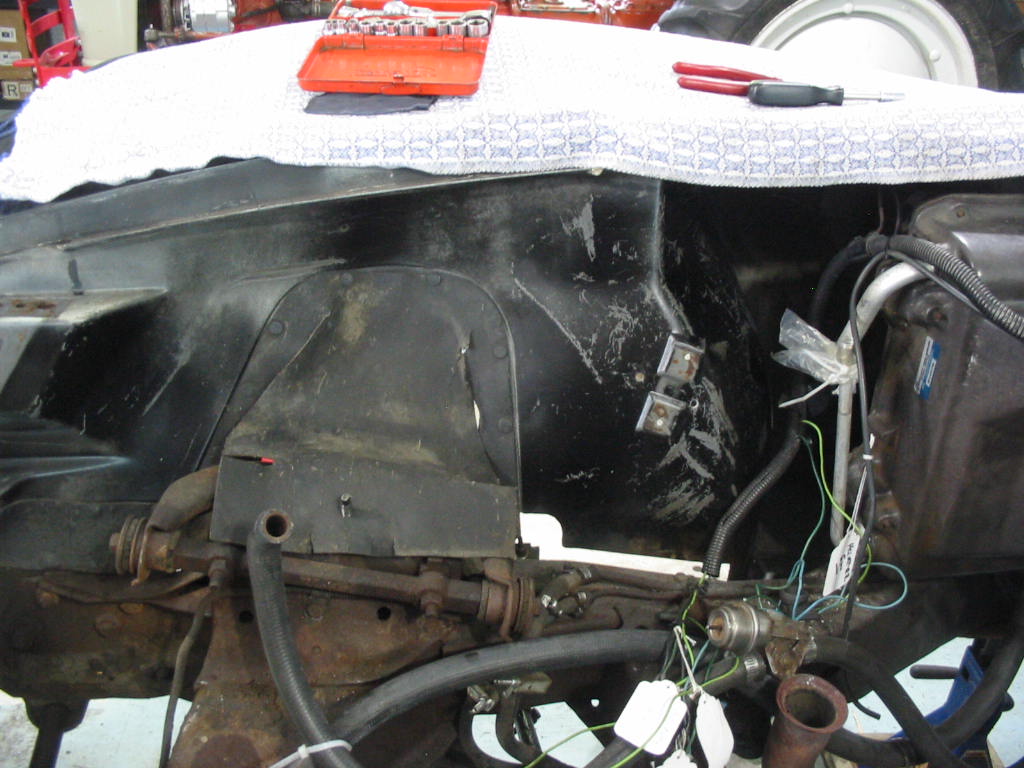
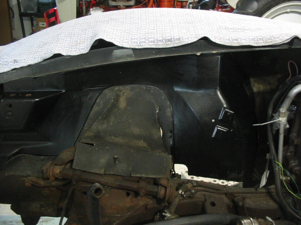
On to cleaning the fender apron before I install the new AC dryer and components. Came out not too bad with a coat of Tremclad semi-gloss paint. The A arm opening cover is sort of OK on the passenger side, but the one on the drivers side is toast so I will have to order a couple in with the plastic rivets to hold them in place.

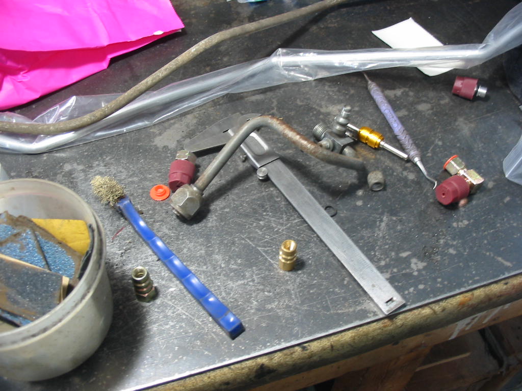
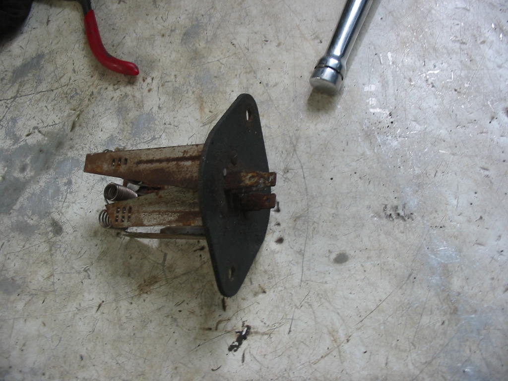
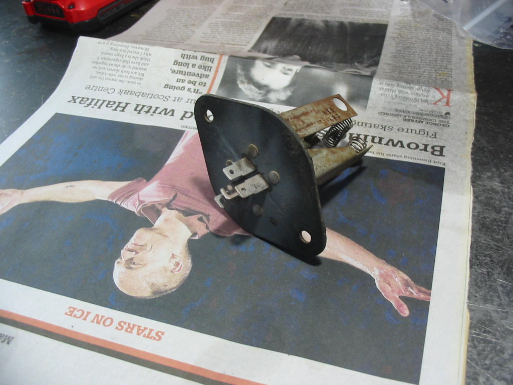
More bits and bobs to clean up. This sensor sits inside the Heat/AC box.

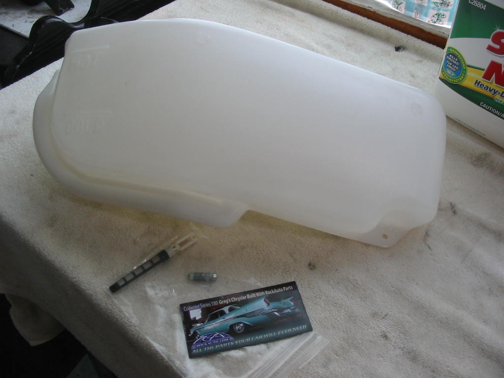
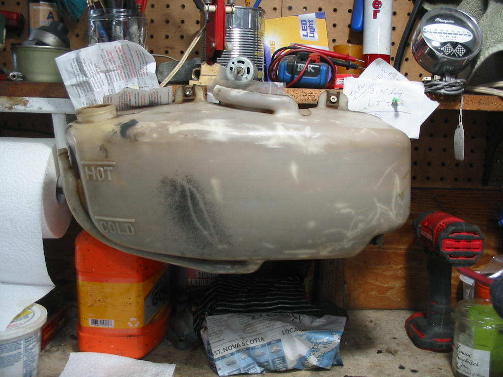
I found a strip of dried up epoxy on the bottom of the recovery tank so I put in some water and sure enough there it is weeping through the plastic seam in the bottom. New ones are available from Northern Corvette for about $50 so I’ve got one on order.

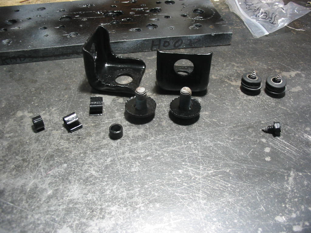
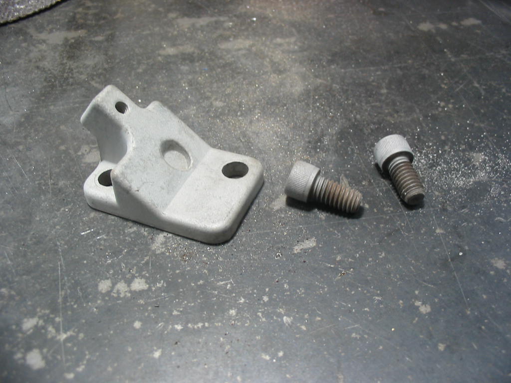
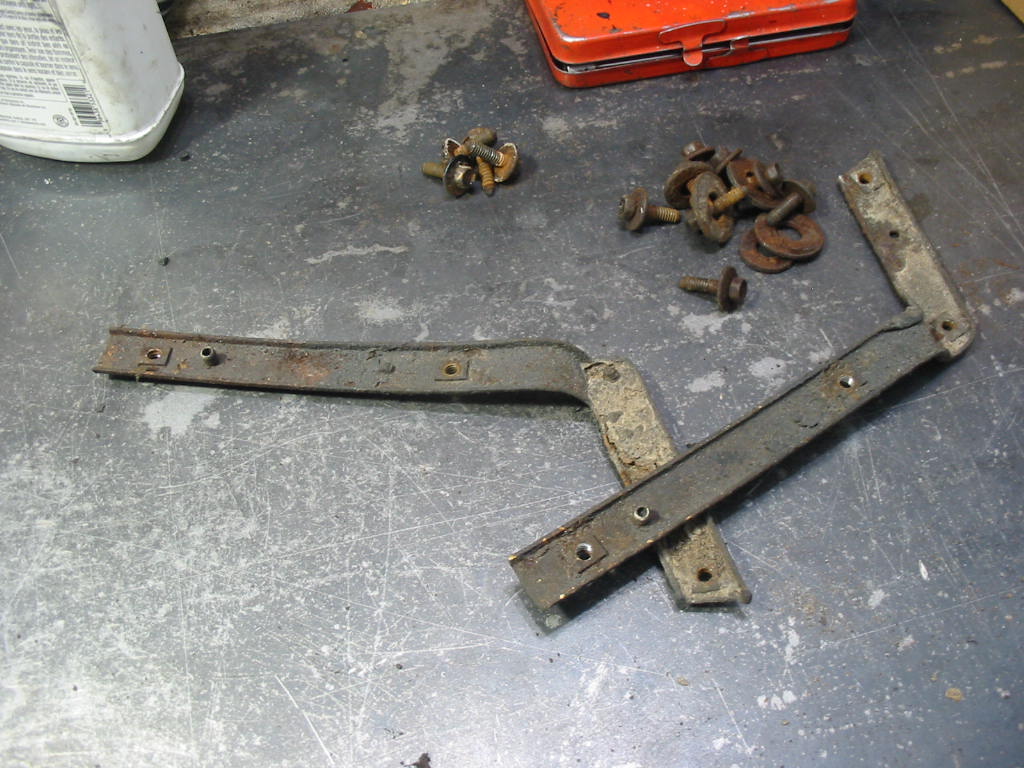
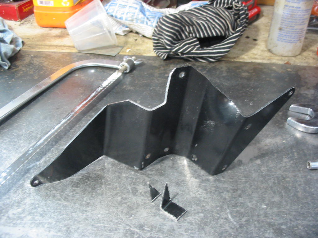
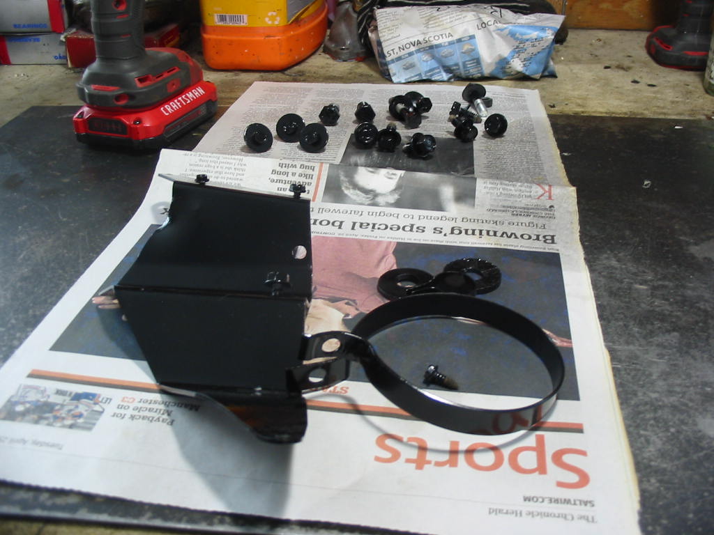
Some of the bits needing paint. I give them a coat of Tremclad rust primer and then two coats of semi-gloss black. Nice a warm upstairs in the garage so it’s good for painting. These are AC brackets and screws for the rad frame and AC condenser.

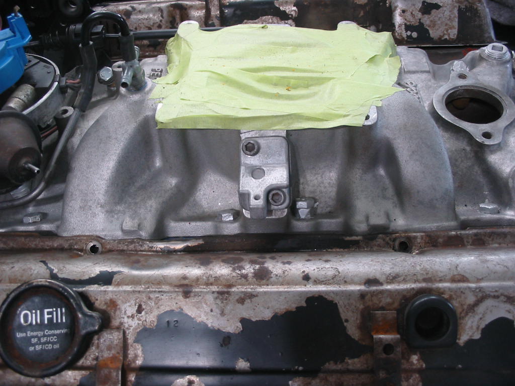
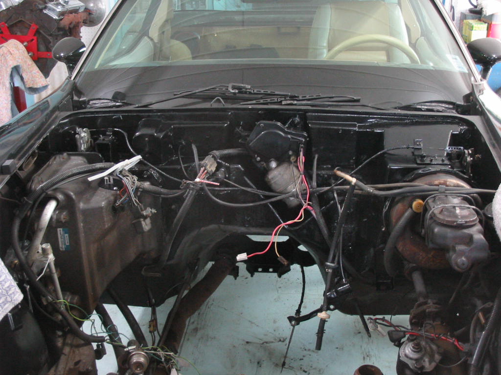
A bit of a bother cleaning the firewall and then giving it a coat of paint. Just have the left side to do then I can go on the the frame cleanup.

Next: more engine bay prep.

Back to the rear suspension for a bit.

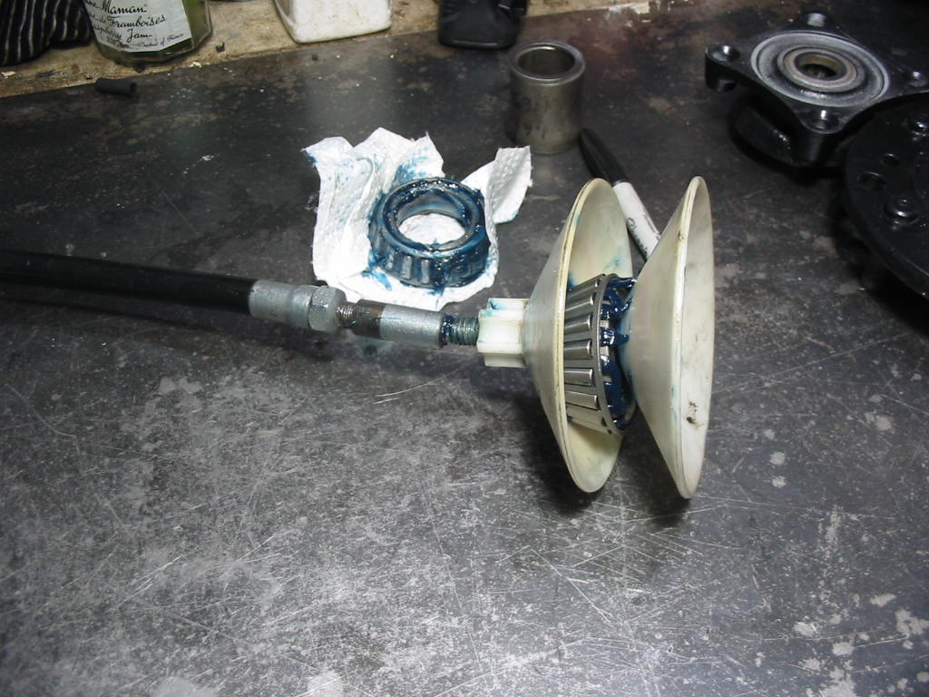
Using my bearing packing tool. Works well. The extra grease inside the bearing centre after the packing I used to smear on the outside and on the bearing cup (race). I’m using wheel bearing grease rather that a chassis general purpose lubricant.

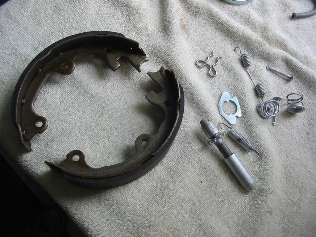
New parking brake shoes and new and old (cleaned and painted) parts ready to go on.

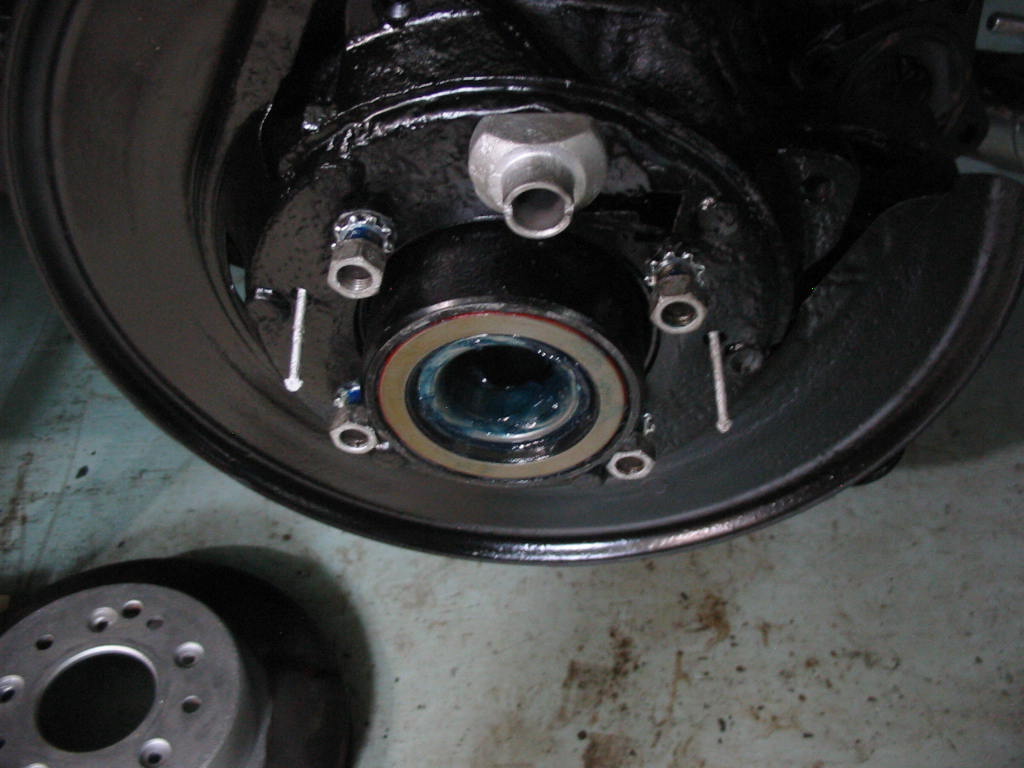
The parking brake shoe retainer pins need to go on BEFORE the backing plate is installed. So I had to pull the plate and re-torque down the nuts with more blue lock tight.

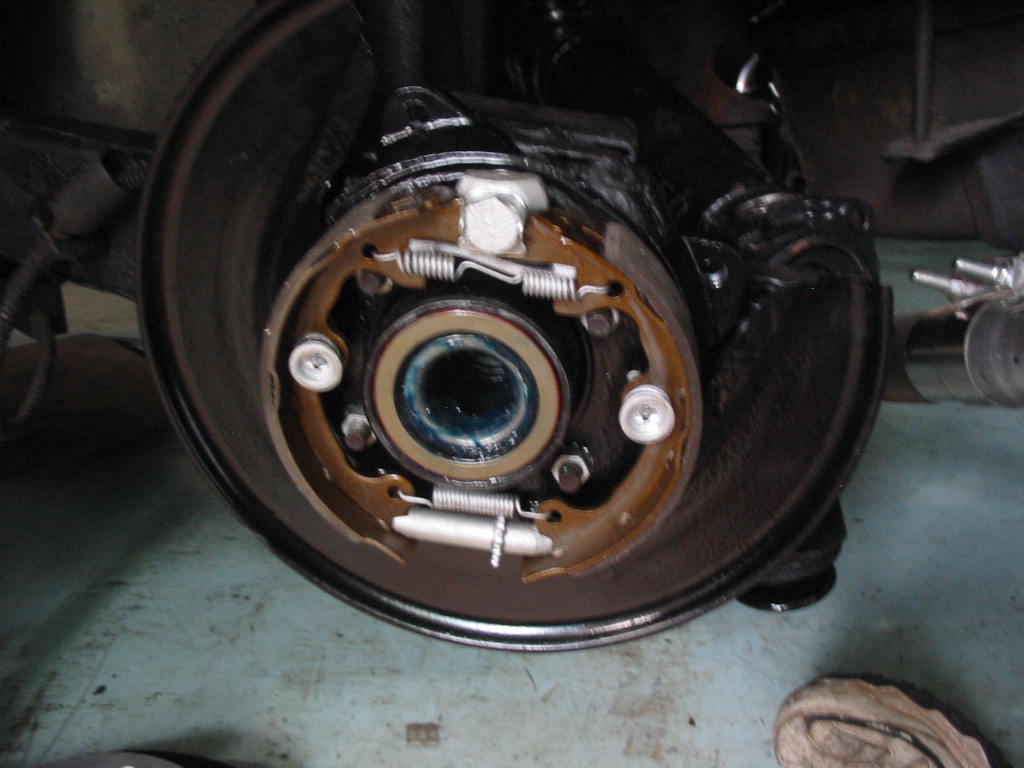
Left side parking brake in place. So much easier to put on without the spindle in place. The outer bearing and seal are also in place at this point.

Rotors back on. Always fun adjusting the parking brake pads through the tiny hole in the rotor!

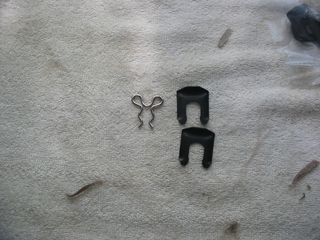
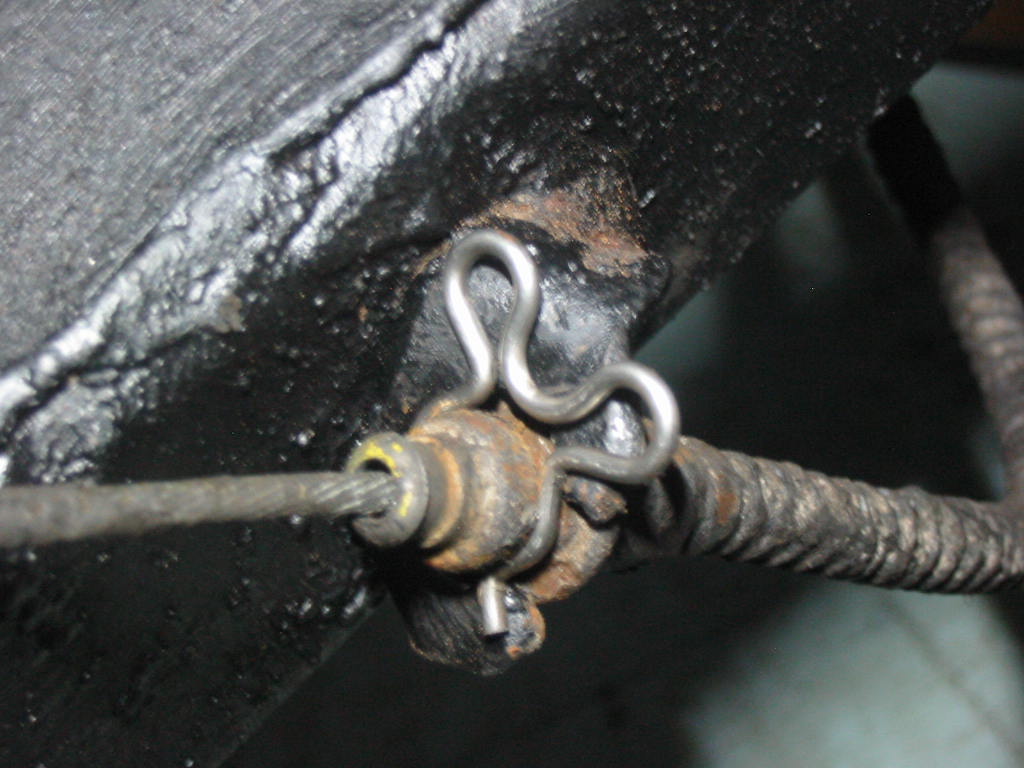
Not happy with the replacement parking brake cable clips. I’m looking for a set of the usual U shaped clips for brake lines that might fit more securely.

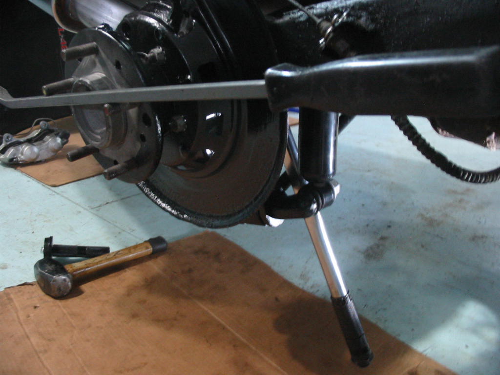
Tightening up the spindle bolt is a challenge. In the end I attached the torque wrench and let it rest against the strut. I then used a pry bar to turn the spindle until the torque wrench clicked. The spindle nut was ‘lubricated’ (hard to keep it clean when slipping it by the greased bearings) so I only torqued to 80 Ft-lbs rather than 100. I have a chart that specifies the torque for bolts dry and lubricated. I figure 80 lubed is as good as 100 dry. I then tightened a bit more until the cotter pin hole appeared.

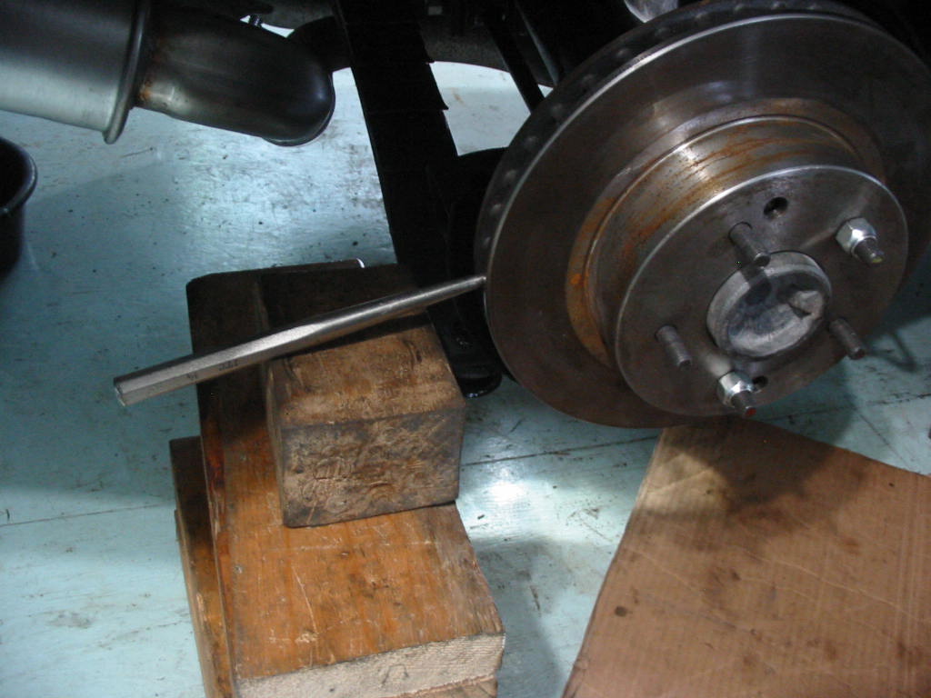
This is how I held the rotor and spindle in place while I torqued the four axle shaft flange bolts to the spindle. I used blue lock tight and 75 ft lbs so they are likely a bit tighter than spec as the blue will act somewhat as a lubricant.

Next: calipers to go on then final tightening of the strut bolts.

Engine and transmission

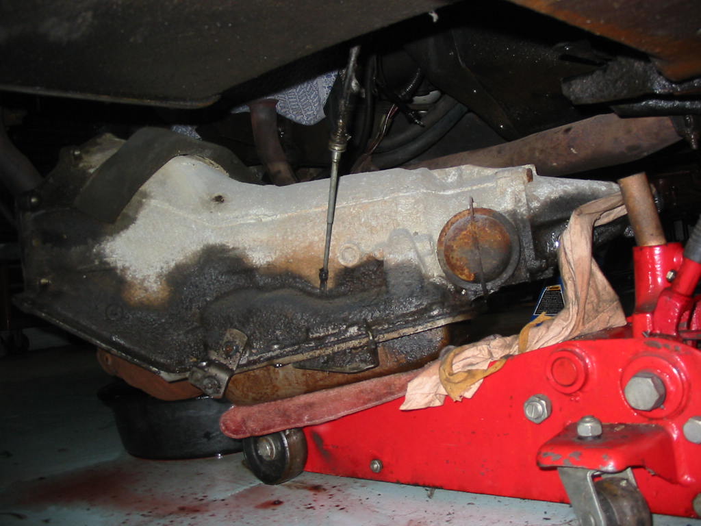
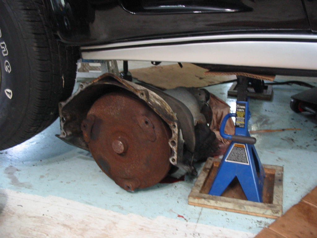
The trans on the jack won’t fit under the car. So it has to come off and be slid out. I could jack the car up to take it out on the jack, but I would have to raise the car a lot and then go through the whole process to get it back down.

In the end I just slid it off the jack and pulled it out. Lots of trans fluid everywhere. Next time I’ll drain the trans while it’s still in the car! Why GM don’t put drain plugs in the transmission pan i don’t know???

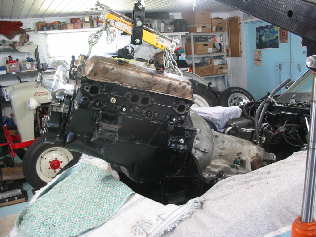
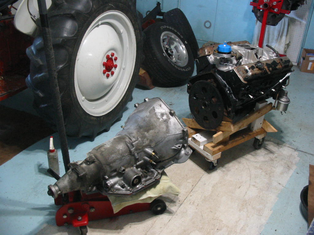
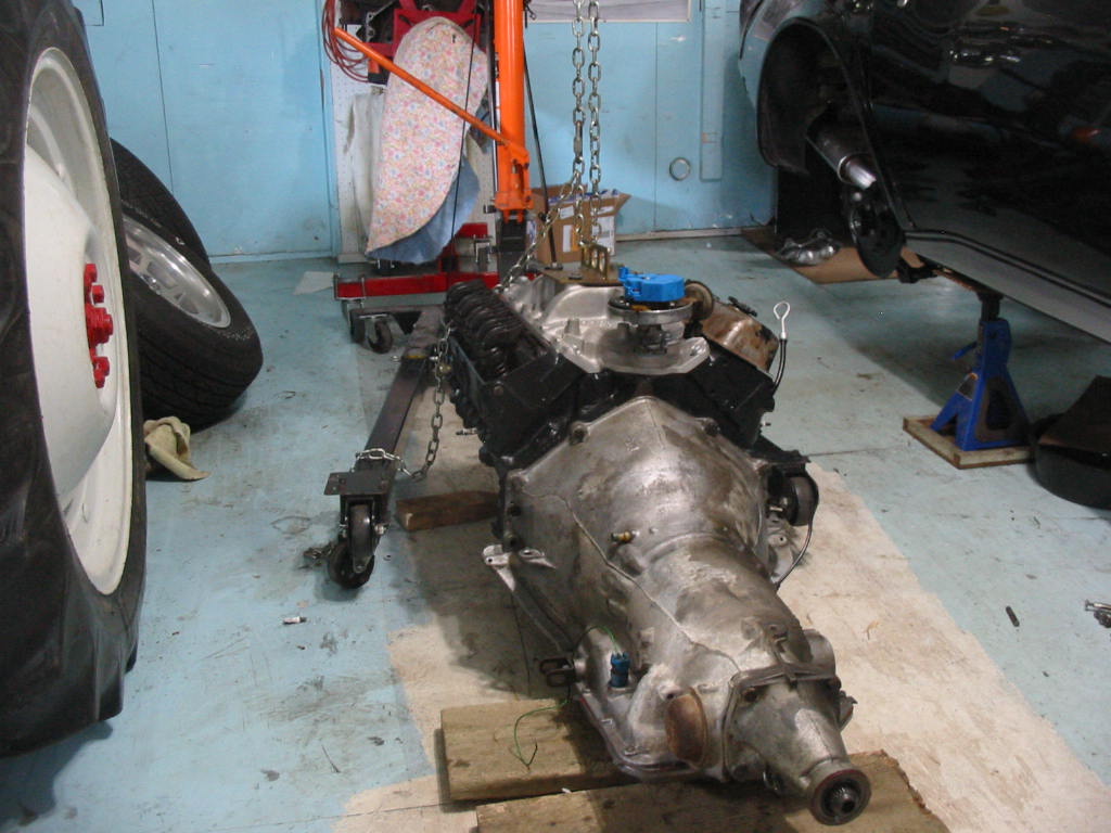
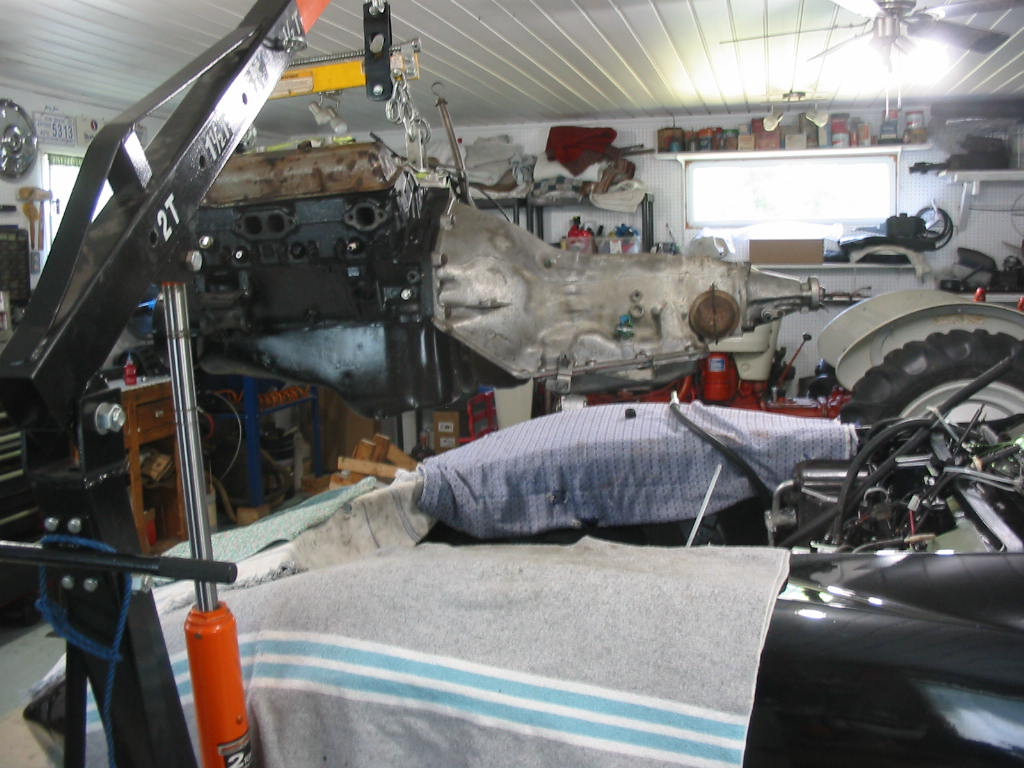
Donor trans on the jack and ready to be connected to the engine. I have decided to attempt putting the trans and engine back as a unit rather than do it separately. Hopefully my 8’ceiling will will allow me to get the engine/trans high enough to go back in as a unit.

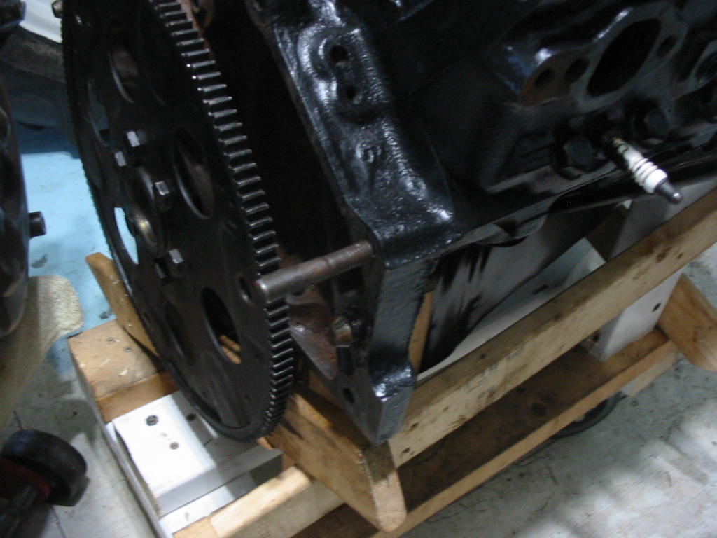
I’ve put a couple of pins in the block to help line up the trans for assembly. The factory alignment pins are short and it is hard to keep one in place while trying to fit the other. these longer pins work better. Get the trans on one pin then use a small vice grip to hold the trans on the pin while getting the other in place.

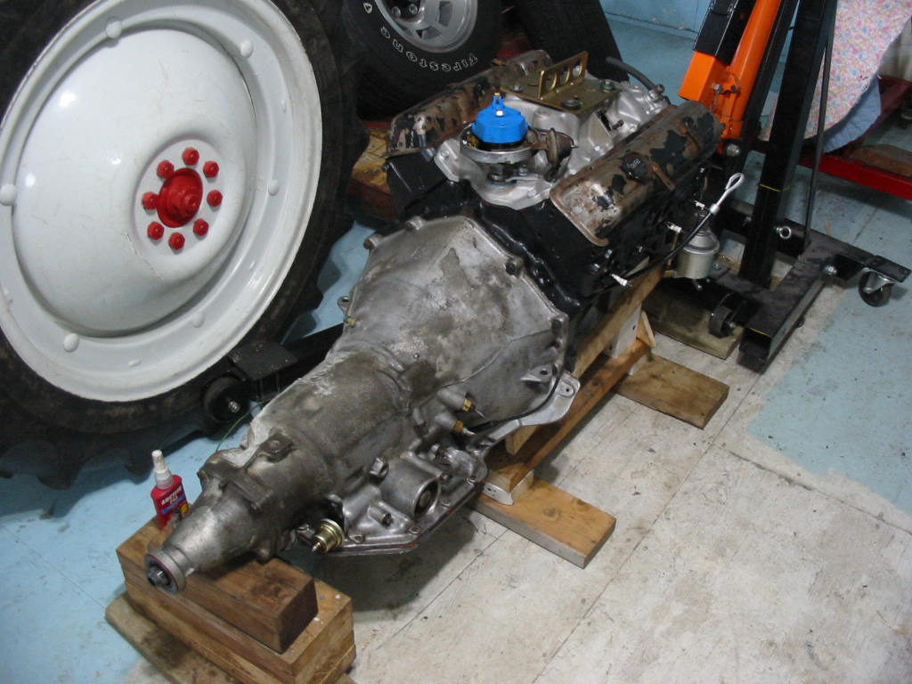
The engine stand was too wobbly so I did the job on the floor holding up the engine with the hoist and lining up the two that way.

Engine back on the stand and a little support for the trans. I’m in the process of transferring the modulator, speedometer gear, shift lever, etc from the original trans.

Next: back to the rear suspension.

Rear suspension re-assembly

(This post is a bit out of sequence. I actually did this work before going on to pull the engine.)

Very hard to get the short shaft u-bolts in place and tightened. No way to get a torque wrench in place for final tightening. So I tightened them as I always did in the old days – a good pull on a regular wrence, but not overly. I put blue lock-tight and new lock washers on all of the u-bolt arms.

Spindle support and parking brake flange in place with nuts torqued to spec – 30 Ft Lbs.

New plastic bushings in place. A real trick to get them on. I had to jack the spring up until the car started to lift then use a 2 X4 to press down the trailing arm enough to get the lower washer and bushing in place. I also had to disconnect the shock and remove the strut bolt before the trailing arm would lower enough.
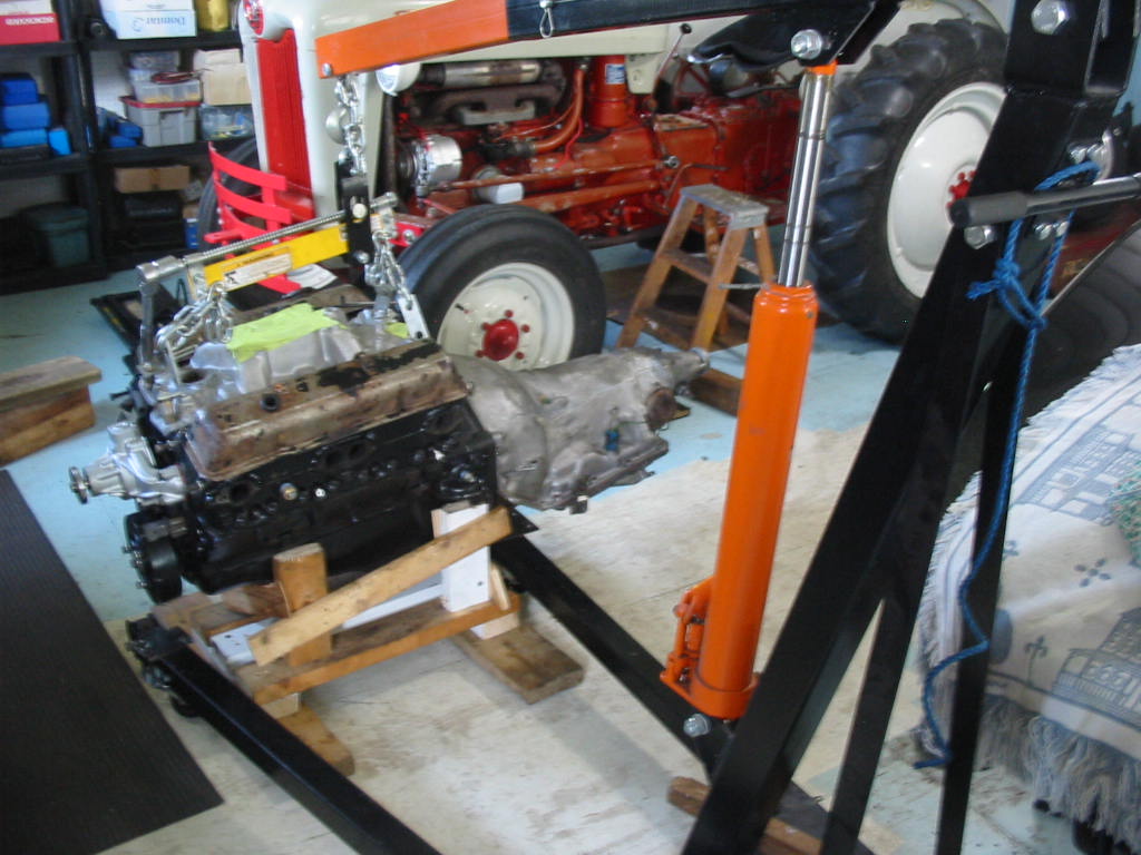
Next: I’m waiting for parking brake parts so I will have to leave the rear suspension for a bit. Now I can get back to the engine swap 🙂

Engine out

Donor engine put on a dolly temporarily.

I’m using a lift plate rather than my adjustable lift tool as I don’t know how much room I’ll have to fully lift the engine over the body. Not like a regular body where I can remove the rad and grille and not have to raise the engine too much to get it out.

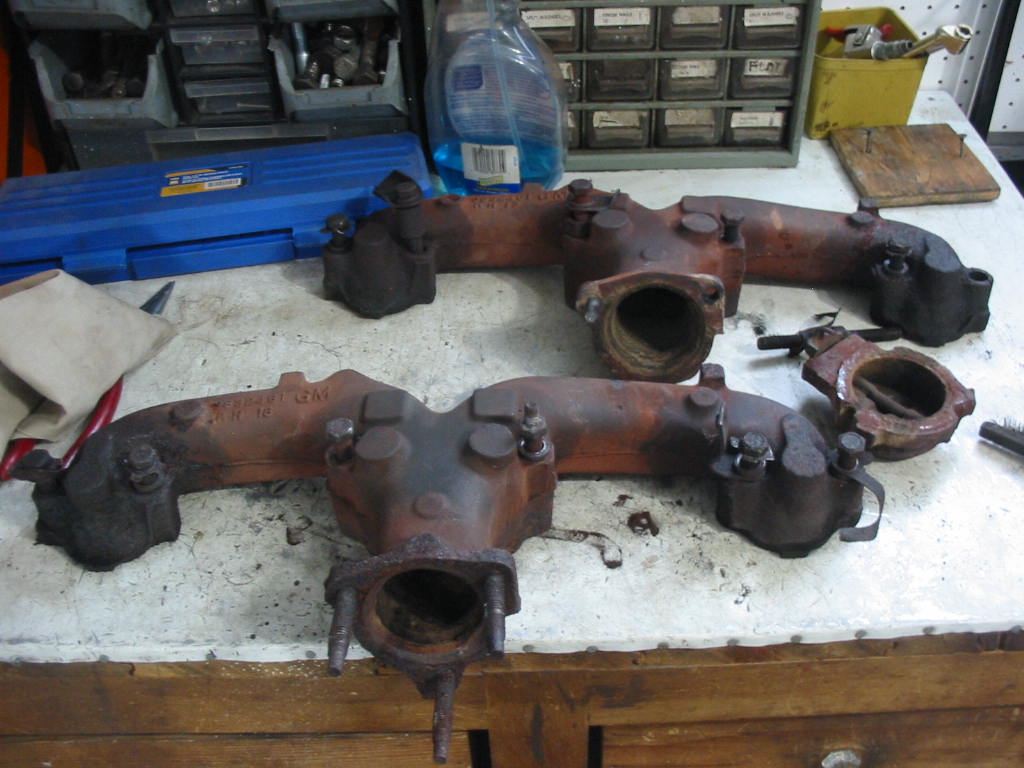
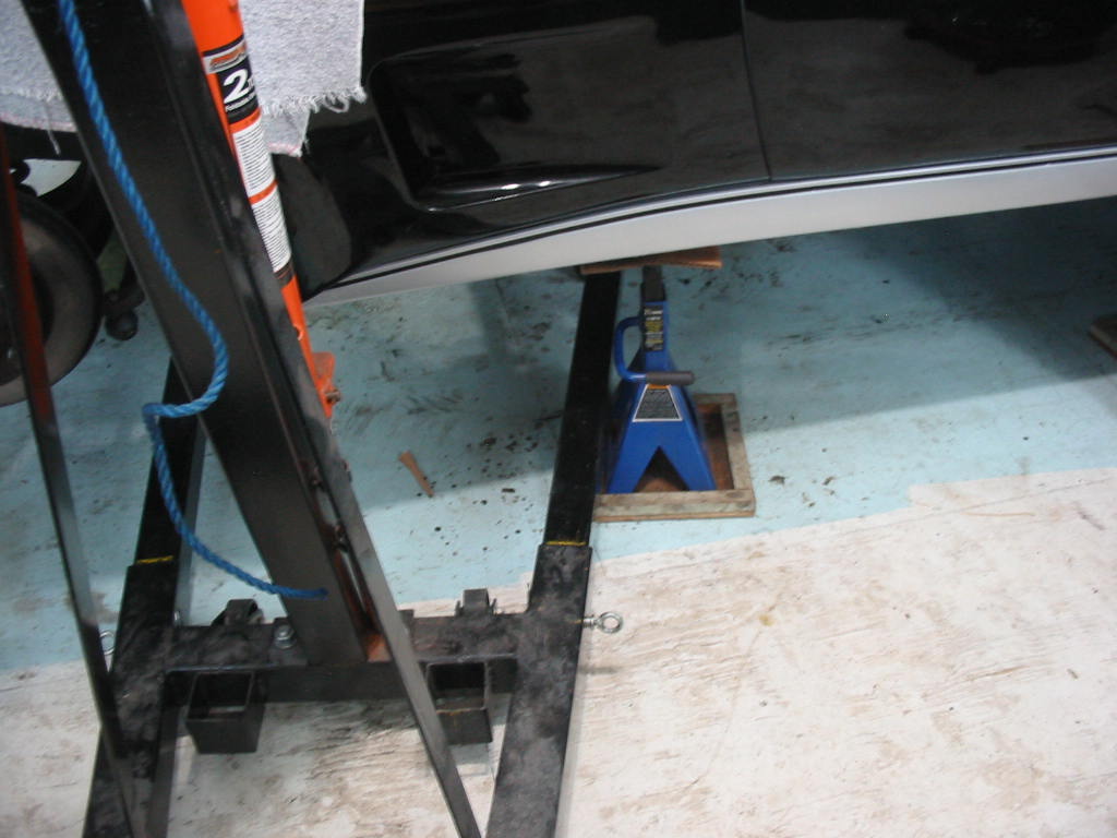
Engine out and high enough to slip over the front. The long exhaust flange studs were a bit of problem getting over the exhaust pipe. Won’t be a problem when I put in the donor engine as it won’t have the exhaust manifolds attached.

Original engine ready for a re-build next winter.

Next: getting the trans out.

Spindle work

This is the rig I borrowed from a fellow C3 Corvette owner Barry Chappell. Going from the left is an idler bearing which is attached to a paint can top with holes to take the spindle studs. The spindle is attached using regular studs put on backwards to flush up against the paint can lid. The drill is attached to the spindle with a short length of coolant hose and a long 1/2″ drive socket on the other end. Then an adapter to fit sockets to a drill. I ran the drill slowly and held a wrapping of 80 grit paper on the bearing surface. I sanded a bit and then checked the fit until the bearing just fit over the spindle snugly. Caution is needed here because it is easy to turn the spindle down too much and that would result in the spindle needing replacement or a sleeve installed – both an added and unnecessary cost.

Spindles taken down and bearings slip fitted on.

Parts with primer and two coats of semi-gloss Tremclad oil based metal paint.

I got the races (cups) started with hammer and brass drift. I then used my bearing and seal seating tool to get them seated tightly. I picked up a seating tool awhile back, but for some reason it is metric. So I just chose one that fits flip it over and use it that way.
Friend Barry was also able to supply a selection of shims and two spacers.

It was then a matter of selecting a combination of shims and spacers that would give me a spindle play of as close to .001 as possible without going below the minimum. On one side I had to flat sand a shim and a spacer to get the play down to were I wanted.

Using my dial gauge and the bench vise I kept trying combinations of shims and spacers. I was able to get a reading of between .001 and .002 which is OK for me. The manual says it can be as high as .008, but that would be really sloppy.

Next: Start of rear suspension re-assembly.

Rear spindle work

Rear spindles finally apart.

The large manual press just couldn’t move the spindle. The spindle was suspended in the metal box as you can see. The two thick steel plates just fit between the spindle flange and the parking brake backing plate (missed getting a shot of that). I bought a big nut for the top of the spindle from Corvette Depot. It is designed to protect the spindle threads and provide a solid surface to hammer on. In this situation it took a 10 lb hammer and some serious hits to finally break the spindle free. We then used a ‘cheese cutter’ under the outer bearing and the sledge to break it free – it also took a few good blows to get it off. The spindle threads were not damaged at all. We did put a couple of spacer washers under the big nut so that it was pressing on the spindle collar under the threaded section.

The bearings were all lightly “boxed” and this one had a serious pit and that needed to be replaced. Lots of old grease in the bearings and they might have gone quite a way before causing problems but this unit would have become more noisy.

These new polyurethane bushings should return the rear end to the proper stance. I would have preferred rubber cushions, but these are all that Corvette Depot had on hand. I’m told these plastic cushions can squeak so I’ll give them a coat of fluid film when they go in.

The spring has likely sagged a little over the years, but the car still stands level so I can go with that. At some point I will remove the spring and put in new plastic liners.

Trailing arm looking a lot better with a coat of rockerguard. I’ll clean up the contact area for the spindle support and then give that area a light coat of Fluid Film to stop any corrosion between the surfaces.

All glass bead blasted. I don’t use sand any more. I find the bead blasting leaves a nicer surface for painting – not so much sanding needed.

There are some heavily pitted areas on the parking brake flange plates. I have given them a coat of epoxy to seal and strengthen them. Now on to painting.

New bearings and seals for both spindles.

Next; turning down the spindles so the bearings will be a ‘slip fit’ rather than needing to be pressed on.

Final disassembly for the rear end

The last parts to be replaced are the spring cushions. These are pretty well at end-of-life.

The jack is held in place by the short piece of 2X4 clamped to the spring.

I was careful in removing the bolts holding the spring cushions. Fortunately they are grade 8 bolts and took the strain of getting the old rusted on castle nuts off. I used lots of penetrating oil to help things along. Cleaned and sandblasted above and ready for paint.

I’ve let the leaf down so I could use the jack on the other side. It is a bit tricky jacking the spring as it lifts the car off the rear jack so I needed to watch that it settled back down right. Easy now to clean and apply rocker guard to the trailing arm and spring ends. Rocker guard is tar like and doesn’t seem to mind any bits of old oil or grease still on the part. It works well on a-arms and other under body metal that is not visible.

The parking brake bracket on the right side was bent and broken off on the bottom. I’m no welder, but I can get a bit of weld on spots like this. As you can see by all the welding spatter the trailing arms are not welded very nicely at the factory. Maybe these are not normal.

The new bushings show just how bad the old bushings had gotten. Ive been told that the harder polyurethane bushings can squeak so I’ll give them a light coating of fluid film on assembly and hopefully that will be enough.

Coated in rocker guard. Brushed on so not as smooth as spray, but the arm is pretty rough itself so no matter really. I”ll clean away any rocker guard on the mating surface for the spindle support and then apply a coat of fluid film when I put it together.

Next: getting at the rear spindles.

One step forward and two back!

One should always read the fine print. My first time installing non-greaseable universals so I assumed that the cups were all loaded with the proper amount of grease. When I had done the job I noticed this tiny note on the universal box flap. No information slip in inside, just this little easily missed note. So no option but to remove all six universals and get them greased.

Not the easiest thing to do to get the new cups out of the yokes. The set that I had greased with anti-seize earlier came out the easiest. I’ll install them with a little grease to ease going in. I squirted one pump from the grease gun, loaded with wheel bearing grease, into each cup.
I also filled the blind holes in each cross arm. I used a needle applicator on the grease gun.

Both short shafts done. I had problems with the flanges bending – even with a 1/4″ steel plate attached – on the last install, but this time all went well after I tighten the plate to the flange good and tight. Only the main drive shaft to finish and hopefully I won’t break either universal. l broke one short shaft universal on the first install and had to buy one from CarQuest. It cost about $53 whereas the ones I purchased from Rock Auto were $35 including shipping.

Back to the pan on the donor trans. I set the gasket in place with red gasket seal on each side – I used a small brush to apply the sealant. I then snugged the screws down. I waited a day and then torqued the screws to 150 inch Lbs per the manual.
Meanwhile a couple of parts arrived from Corvette Depot. Two new rear spindle nuts and a fitting that goes over the spindle threads. That will save the threads when I put the unit in a press to remove spindle from the spindle support.
3/4″ X 20 tap and die arrived. Cost a little over $20 from Amazon. I need these to clean up the rear spindles.

I cleaned up one spindle and the new nut spins on easily. Not so for the cap. I was a tight fit almost like a tapered plumbing fit. So I ran the tap through it and it then fit nicely on the spindle. It will protect the threads when I try to press out the bearings – much better than reversing the castle nut and threading it back on the spindle top. Supposedly you can hammer the spindle with this covering nut to drive it out of the bearings, but I prefer to press them out even if I damage the dust cover (flange plate) a bit.

Next: on to replacing the spring cushions.

Moving along

One short shaft done and one to go.

Stopped by a local Chev dealer to get the positraction additive and some of their hypoid gear oil. They only had synthetic so I hope it doesn’t leak too much. Pricey stuff at $22 for the additive and $32 for a litre of hypoid gear oil. If this doesn’t clear up the chatter then I’m in deep do-do!

Oil changed in the differential. Much easier with the short shaft out of the way and the spindle assembly and caliper also removed. Still it takes quit a bit to suck out all the old oil with a vacuum pump. Quicker to get the new fluid and additive in using a squirt cap and small length of tubing on one of the litre bottles – in the photo above this one.

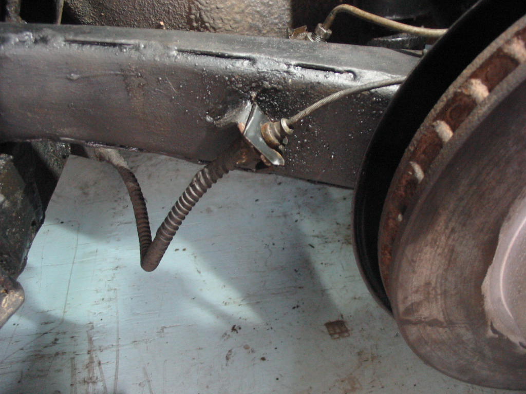
Time to clean up the trailing arms. really rough welding on the various metal sections. I managed to break off the clip holding the parking brake cable to the frame bracket on the forward side of the arm. The bracket was bent from some happening the car experienced in the past.

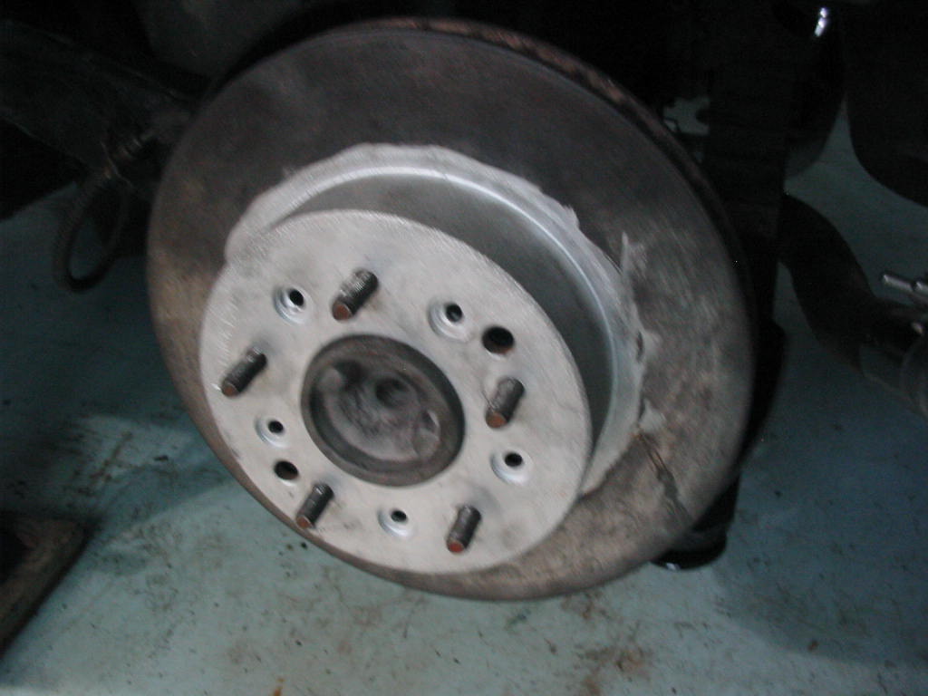
Sanded off the corrosion on the studs which should help with refitting the spindle assembly. I also ran a tap on the to straighten and clean the threads.

Once the trailing arms are cleaned up I’m going to replace the spring bushings with new polyurethane mounts. I would have preferred rubber, but it was all that was easily available . They shouldn’t make the ride any harsher as they might if I did the front end with them.