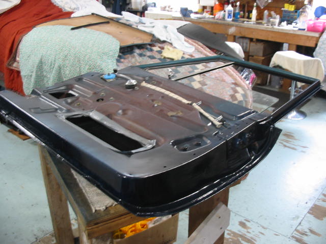
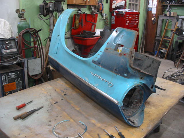
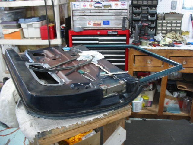
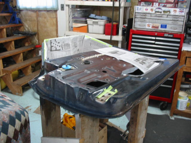
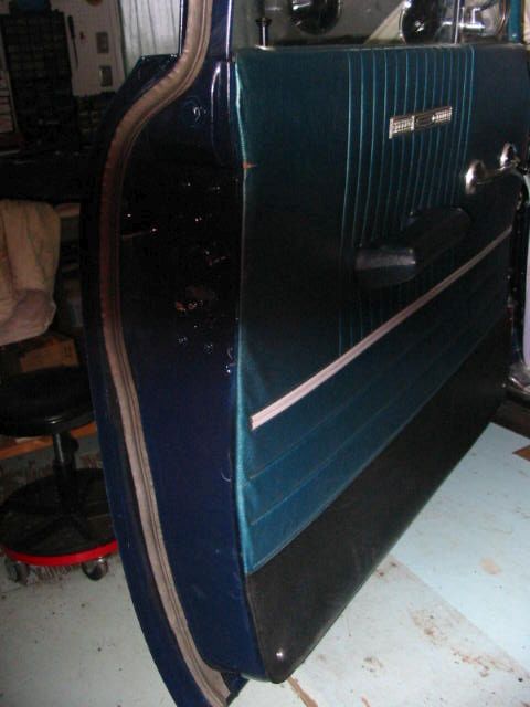
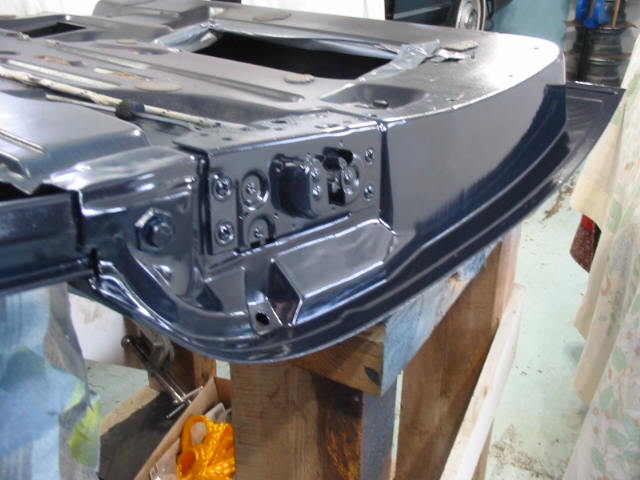
Ready for painting.


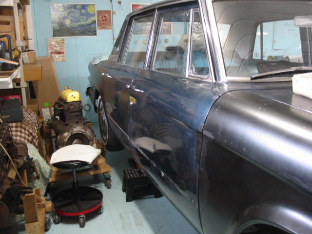
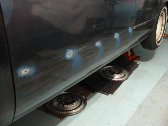
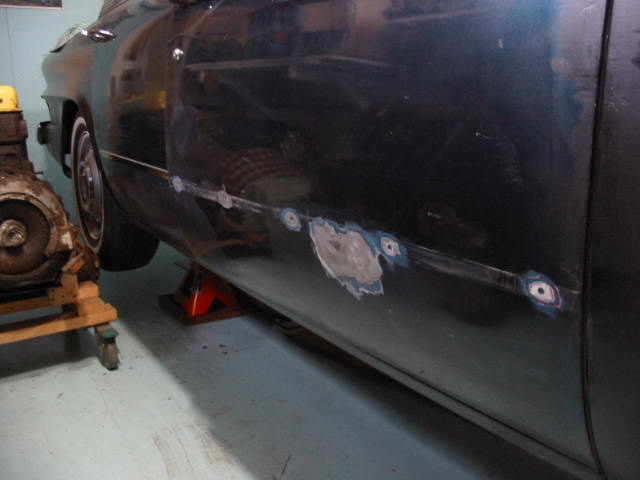
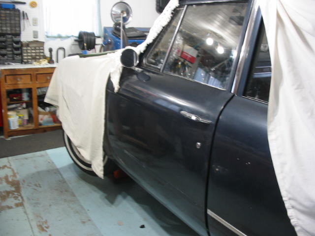
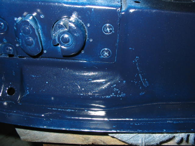
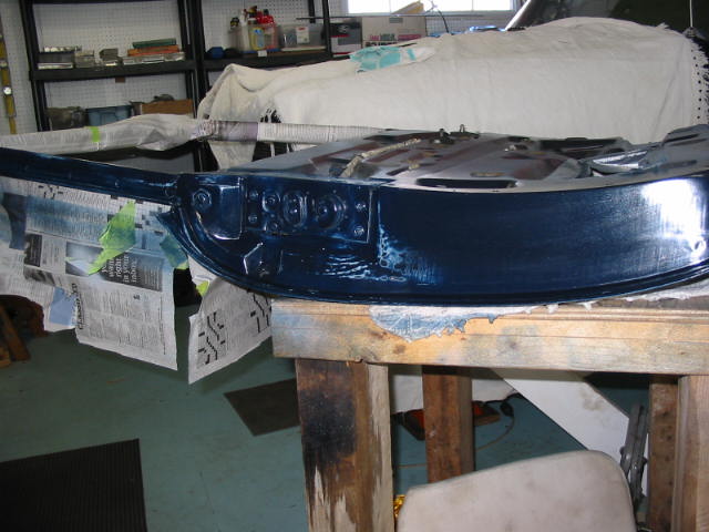
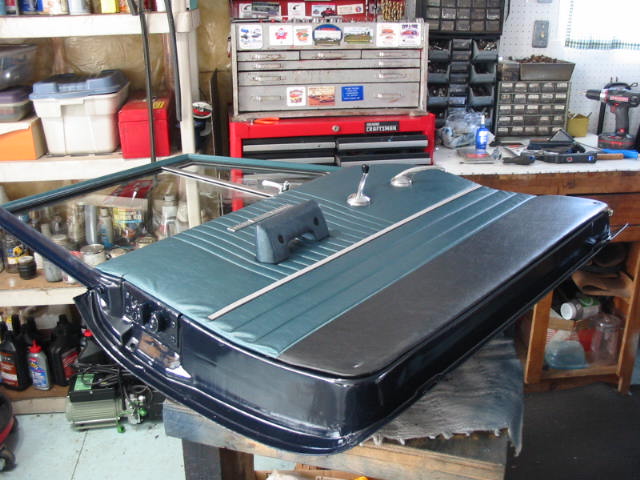
Hard to see the paint jobs, but I painted the driver’s door with the original Richelieu Blue metallic. Turned out OK with a couple of coats of paint and a couple of clear coat. I used acrylic enamel for both the paint and the clear. The passenger door is done in satin black as I also painted the new fenders and rockers.
The car is now ready to get on the road as soon as the salt is washed away:-)

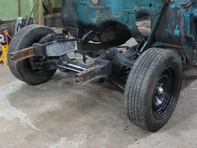
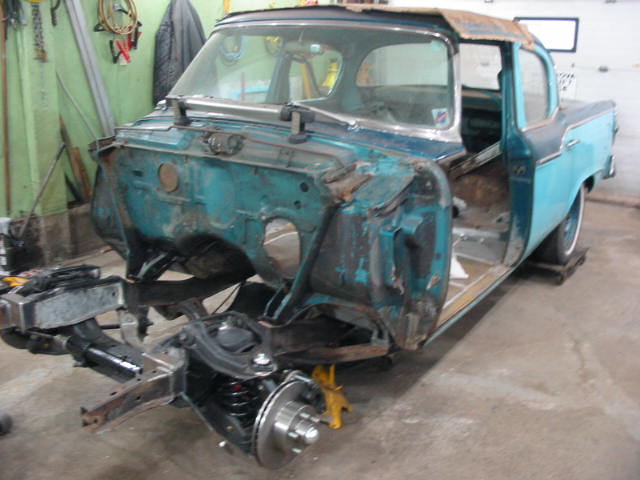
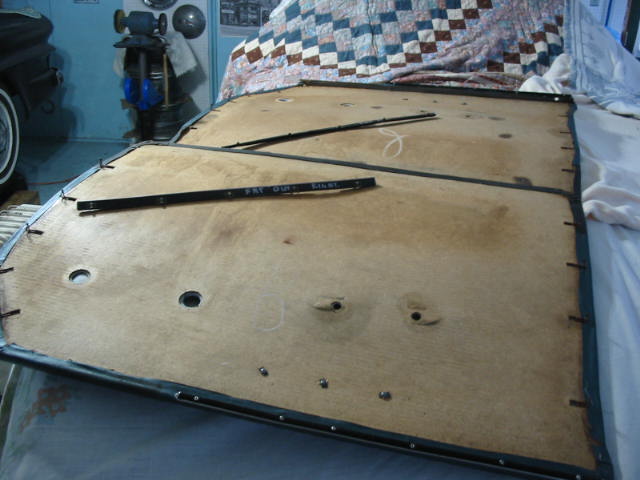
Meanwhile my buddy Don is working on his ’57 Studebaker project car. Nice job of patching the inside of the fender.

Less patching needed on the passenger side fender.

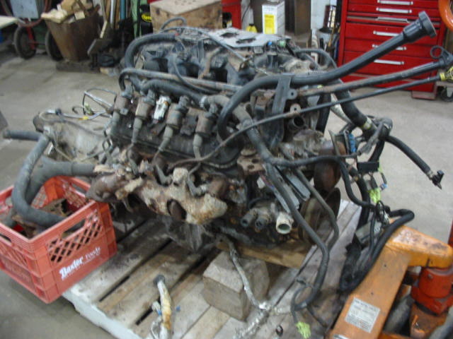
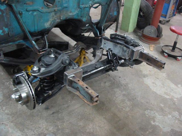
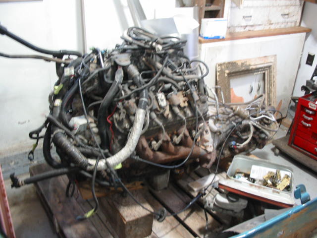
There are always hitches in these projects. This is the heavy duty 3 spd auto with overdrive that is attached to the 350 LS Don is planning on putting in the Stude. You can’t see it but at least three of the mounting ears are cracked! It is a one piece case so to repair will mean finding another trans and swapping out the internals. Not an easy job to find a donor and do the swap. Happily Don has a 700R4 three speed OD trans from a Firebird that he recently bought, stripped and junked. This might be better as the 700R4 is smaller than the HD trans now on the engine and it will be easier to fit in the Stude.
Next: waiting on a donor 350 for the ’79 Chevy